

The RGB LED Circuit is an easy electronics project for beginners. This RGB LED Circuit shows how red, green, and blue LEDs can combine to produce multiple colors. With a few components, you can make an RGB LED Circuit using a transistor and resistors. This RGB LED Circuit tutorial includes a complete BOM list, working principle, and circuit diagram.
Whether you’re a student or hobbyist, this RGB LED Circuit helps you understand how color mixing works. Learn how to test the RGB LED Circuit and how to assemble it properly. The RGB LED Circuit is ideal for DIY lighting and small decoration projects. This RGB LED Circuit guide is detailed, easy to follow, and provides practical learning about LED circuits.
Introduction
The RGB LED Circuit is one of the simplest yet most interesting electronics projects that every beginner should try. It helps you understand how red, green, and blue light can be combined in various ways to produce different colors the same principle used in TV screens, monitors, and digital displays.
In this project, we’ll use a transistor, resistors, and an RGB LED to build a basic color-mixing circuit. You don’t need a microcontroller or any complex IC; this project is purely analog and teaches the core concept of LED color blending and current control using basic components.
Materials for the Project
| S.No. | Component Name | Quantity | Description / Value | Buy Link |
|---|---|---|---|---|
| 1 | RGB LED (Common Cathode or Common Anode) | 1 | 5mm or 10mm RGB LED | Buy Link |
| 2 | NPN Transistor (e.g., BC547 or 2N2222) | 1 | General-purpose NPN transistor | Buy Link |
| 3 | Resistors | 3 | 220Ω – 1kΩ (for current limiting) | Buy Link |
| 4 | Breadboard or Perfboard | 1 | For circuit assembly | Buy Link |
| 5 | Jumper Wires | As required | Male-to-male wires | Buy Link |
| 6 | 9V Battery with Connector | 1 | Power supply | Buy Link |
Circuit Diagram Explanation
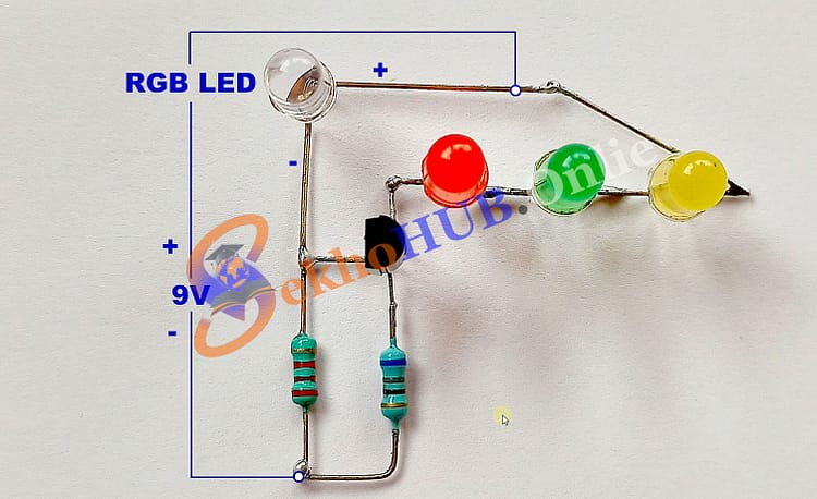
The RGB LED Circuit consists of one RGB LED connected through three current-limiting resistors to the collector terminal of an NPN transistor. Each color channel red, green, and blue is controlled by connecting its resistor to the transistor and the positive supply line.
Working Flow:
The ground is connected to the NPN transistor’s emitter.
The collector connects to the negative terminal of the RGB LED.
The base of the transistor is driven through a small resistor connected to the RGB LED’s control pin.
When a small current is applied to the transistor’s base, it allows a larger current to flow from collector to emitter, turning ON the LED.
Download Circuit Diagram
How the RGB LED Works
An RGB LED has three LEDs combined inside a single package — one each for Red, Green, and Blue.
In a Common Cathode RGB LED, all negative terminals are connected together internally.
In a Common Anode RGB LED, all positive terminals are joined internally.
Each color can be independently powered, and by controlling the voltage or current for each color, you can produce virtually any color in the visible spectrum.
For example:
Applying equal voltage to all three → White light.
Applying more current to red and green → Yellow.
Adjusting the ratio between the three → Custom color shades.
Working Principle
The transistor here acts as a current amplifier.
A small signal at the base allows a larger current to flow from collector to emitter, turning ON the LED.
Each resistor limits current to prevent the LED from burning out.
By manually or electronically controlling the transistor base signals, you can turn each color channel ON or OFF — achieving full-color combinations.
This analog RGB LED circuit is a simple demonstration of how color control works without needing PWM or microcontrollers.
Applications of RGB LED Circuit
Decorative lighting projects
Indicator lamps with multiple color outputs
DIY LED lamps and artistic displays
Color mixing experiments for students
Educational demonstrations for electronics basics
Prototype color sensors or light controllers
Troubleshooting Tips
If one color doesn’t light up, check that LED pin’s connection and resistor.
Make sure the RGB LED type (common anode/cathode) matches your circuit connection.
Verify the transistor orientation — base, collector, and emitter must be connected correctly.
Use a current-limiting resistor to avoid LED damage.
Check the battery voltage; a weak battery might cause dim output.
Frequently Asked Questions (FAQs)
Q1. Can I use any type of RGB LED for this circuit?
Yes, but check whether it’s a common anode or common cathode RGB LED. The wiring changes slightly.
Q2. Why do we need a resistor for each LED color?
Each LED color has a different forward voltage, so individual resistors ensure proper current limiting.
Q3. Can I control the colors automatically?
Yes. You can later replace manual switches with an Arduino or 555 timer circuit for automation.
Q4. What power supply is suitable?
A 9V battery or a regulated 5V–9V DC adapter works perfectly.
Q5. Can this circuit drive high-power RGB LEDs?
No. For high-power RGB LEDs, use power transistors or MOSFETs and a 12V DC supply.
Conclusion
Building a Basic RGB LED Circuit is an excellent starting point for anyone exploring electronics and LED color theory. This project demonstrates how three simple LEDs can combine to form almost any visible color using resistors and a transistor.
Once you master this basic version, you can easily upgrade it by adding microcontroller-based control, PWM dimming, or automatic color sequences.