

how to build an LED dimmer using a 555 timer IC and PWM
[Sekhohub.online]
Here’s a great tutorial showing how to build an LED dimmer using a 555 timer IC and PWM.
How It Works
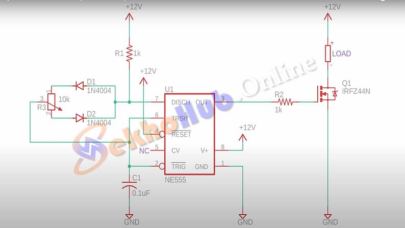
1. Pulse Width Modulation via 555 Timer
A 555 timer generates a square wave (PWM) whose duty cycle (ratio of “on” vs. “off” time) is adjusted with a potentiometer.
This signal controls a MOSFET, which switches current through the LED at high speed. The human eye perceives dimming, but the LED remains either fully on or off during each cycle.
2. Why PWM Is Preferred
Color stability: PWM keeps the LED at full current during the “on” phase, avoiding color shifts common with analog dimming.
- Efficiency: Less heat loss compared to resistors or voltage reduction.
Download Circuit Diagram
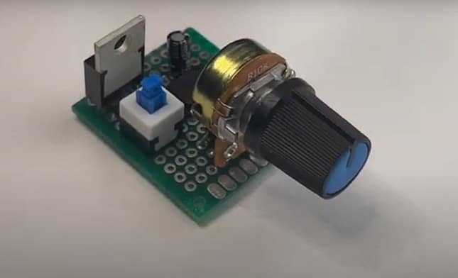
Materials for the Project
| Component | Value | Notes |
|---|---|---|
| 555 timer (NE555) | 1 | Generates PWM |
| Potentiometer | 10 kΩ | Controls brightness |
| Diodes | 2 × 1N4007 | Separate charge/discharge paths |
| Timing capacitor | 0.1 µF | Sets base PWM frequency (~500 Hz–2 kHz) |
| Gate resistor | 2X 1K | Between pin 3 and MOSFET gate |
| MOSFET | IRFPZ44N | Capable of high current |
| LED strip | 12 V | Supply-matched to your system |
| Supply voltage | 5–15 V | Matches LED strip & MOSFET rating |