

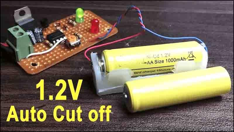
⚡ How to Make 1.2V Automatic Battery Charger Using LM393 & LF33CV IC
This project covers a simple automatic battery charger circuit for 1.2V NiMH or NiCd cells. The system uses the LM393 comparator and the LF33CV voltage regulator IC to build a compact, efficient, and cost-effective solution with auto cut-off.
What is the LM393 IC?
LM393 is a dual comparator IC that compares input voltages and changes its output based on the difference. It operates with a single power supply and is ideal for voltage detection circuits.
⚙LM393 Features:
- Dual independent voltage comparators
- Wide supply range: 2V to 36V
- Low input offset voltage
- Open-collector output (requires pull-up resistor)
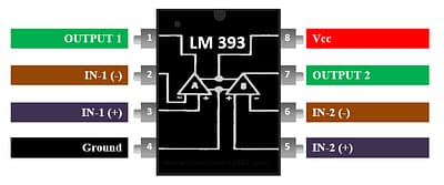
LM393 Pin Configuration:
| Pin No | Name | Description |
|---|---|---|
| 1 | OUT1 | Output of Comparator 1 |
| 2 | IN1- | Inverting input of Comp 1 |
| 3 | IN1+ | Non-inverting input Comp1 |
| 4 | GND | Ground |
| 5 | IN2+ | Non-inverting input Comp2 |
| 6 | IN2- | Inverting input Comp2 |
| 7 | OUT2 | Output of Comparator 2 |
| 8 | Vcc | Power Supply (+) |
What is the LF33CV IC?
LF33CV is a 3.3V fixed linear voltage regulator in the TO-220 package. It is used here to supply a safe and steady voltage to charge the 1.2V battery with controlled current.
⚙ LF33CV Features:
- Fixed 3.3V output
- Up to mA current output
- Internal current limiting
- Thermal shut-down and safe area protection
LF33CV Pin Configuration:
| Pin No | Name | Description |
|---|---|---|
| 1 | IN | Input Voltage (5–9V) |
| 2 | GND | Ground |
| 3 | OUT | Regulated 3.3V Out |
Materials for the Project
- 1x LM393 IC
- 1x LF33CV IC
- 1x BC557 TRANSISTOR
- 4x 1N4148 DIODES
- 2x LEDS
- 2x 10uF CAPACITORS
- 1x 5K TRIMPOT
- 1X 1 OHM RESISTOR
- 2X 100 OHM RESISTORS
- 1X 470 OHM RESISTOR
- 1X 10K RESISTOR
- 1x 2 PIN TERMINAL BLOCK
- PREF BOARD
- JUMPER WIRES
Download Circuit Diagram
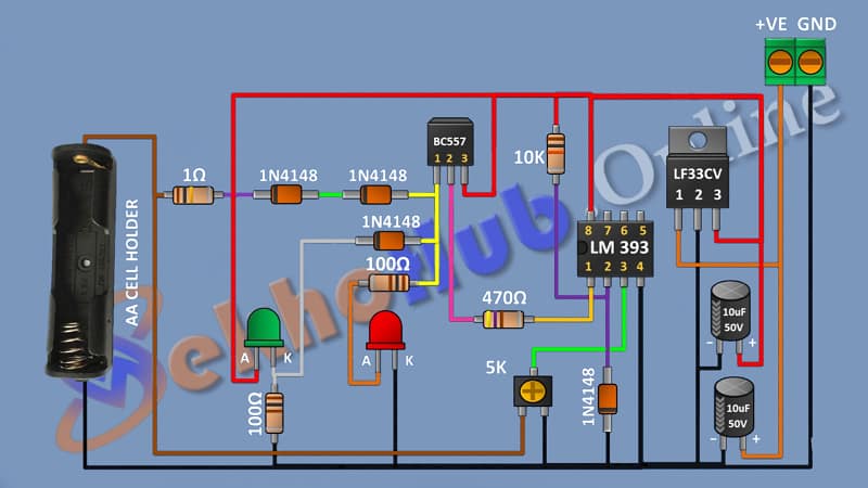
Circuit Diagram Explanation
- Power Supply: A 5V to 9V DC adapter powers the circuit.
- Voltage Regulation: LF33CV reduces voltage to 3.3V.
- Voltage Divider: A resistor divider from the battery provides feedback to LM393.
- Comparator Action: LM393 compares battery voltage to reference (set using potentiometer).
- Charging Control: When voltage exceeds 1.4V, the output of LM393 goes LOW, turning OFF the charging transistor.
- LED Indicator: Shows when battery is charging.
Working Principle
- When battery voltage is below 1.4V, the LM393 output is HIGH → the transistor conducts → charging continues.
- When the battery is fully charged (≥1.4V), the LM393 output switches LOW → the transistor cuts off → the battery stops charging.
- A diode prevents reverse current flow.
⚡ Specifications
- Input Voltage: 5V to 9V DC
- Output Voltage: Approx. 1.3V to 1.4V (after diode drop)
- Current Output: Up to mA (regulated by LF33CV)
Applications
- 1.2V rechargeable NiMH/NiCd chargers
- LED light battery backup
- DIY electronic kits with auto cut-off feature
Tips
- Use Schottky diode for better drop (~0.3V)
- Ensure proper heat dissipation for LF33CV
- Adjust reference voltage with potentiometer for different batteries