

How to Make a 100W Stereo Amplifier at home
Using Components and Circuit Diagrams
If you are passionate about building high-power audio systems, a 100W stereo amplifier is a great project to take on. It delivers clear, powerful sound for home audio setups, DIY speaker systems, or even small public address systems. In this guide, we will go step by step through the process of making a 100W stereo amplifier using readily available transistors, diodes, capacitors, and other discrete components.
We’ll cover the circuit design, components list, wiring details, and assembly tips so you can build a reliable and efficient amplifier.
Understanding the 100W Stereo Amplifier
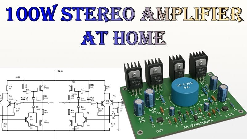
A stereo amplifier has two identical channels, one for the left speaker and one for the right. Each channel in this project is capable of delivering around 50W of RMS power, combining to make a total of 100W output. The design is based on complementary power transistors TIP3055 (NPN) and TIP2955 (PNP) for each channel, which handle high current and power dissipation.
The amplifier works by boosting the low-level audio signal from a source such as a mobile phone, computer, or preamp. The boosted signal is then sent to the speakers, producing clean and loud sound.
Materials for the Project
Here is the complete list of components you’ll need. The quantities below are for the stereo version. If you plan to make a mono version, the quantities will be halved, except where noted.
1. Power Transistors
| Qty | Part Number | Description | Notes |
|---|---|---|---|
| 1 | TIP3055 | NPN Power Transistor | Output stage |
| 1 | TIP2955 | PNP Power Transistor | Output stage |
| 1 | TIP45 | NPN Power Transistor | Driver stage |
2. Small Signal Transistors
| Qty | Value | Voltage Rating | Type |
|---|---|---|---|
| 2 | 2200 µF | 50V | Electrolytic |
| 1 | 100 µF | 50V | Electrolytic |
| 2 | 10 µF | 50V | Electrolytic |
3. Diodes
| Qty | Part Number | Description | Notes |
|---|---|---|---|
| 2 | 1N4007 | Rectifier Diode | Bias & protection |
| 4 | 6A10 | Power Rectifier Diode | Power supply section |
4. Capacitors
| Qty | Value | Voltage Rating | Type |
|---|---|---|---|
| 2 | 2200 µF | 50V | Electrolytic |
| 1 | 100 µF | 50V | Electrolytic |
| 2 | 10 µF | 50V | Electrolytic |
5. Resistors
| Qty | Value | Power Rating | Notes |
|---|---|---|---|
| 2 | 0.33Ω | 5W | Emitter resistors |
| 3 | 3.3 kΩ | 1W | Bias network |
| 1 | 33Ω | 1/4 W | Feedback network |
| 1 | 220Ω | 1/4 W | Bias network |
| 1 | 22 kΩ | 1/4 W | Feedback network |
| 1 | 27 kΩ | 1/4 W | Feedback network |
6. Power Supply
| Qty | Part Number / Spec | Description |
|---|---|---|
| 1 | Transformer 25-0-25V, 8A | Power transformer |
7. Miscellaneous
| Qty | Part Name | Notes |
|---|---|---|
| — | Heat Sinks | For TIP3055, TIP2955, TIP45 |
| — | PCB Board | Stereo layout |
| — | Jumper Wires | Signal and power connections |
| — | Screws and Spacers | Mounting hardware |
Download Circuit Diagram


Gerber Zip Files power amp
Gerber Zip Files power amp
Circuit Overview
The heart of this amplifier is a Class AB push-pull output stage using TIP3055 and TIP2955. These two complementary transistors handle the positive and negative halves of the audio waveform, ensuring high efficiency with low distortion.
The BC557 transistors work as the input and driver stages, providing signal amplification before the power stage. The TIP45 is used as a driver or pre-output stage transistor to boost the signal further.
The 1N4007 diodes provide polarity protection and bias stability, while the 6A10 diodes form part of the rectification system in the power supply, converting AC from the transformer into DC for the amplifier.
Power Supply Section
The power supply uses a 25-0-25V, 8A transformer. After rectification through the 6A10 diodes, the supply provides a split ±35V DC output, which is ideal for this amplifier design.
Large filter capacitors (2200 µF, 50 V) smooth the rectified voltage to reduce ripple, ensuring a clean power source for the amplifier. Proper smoothing is important to avoid hum or noise in the audio output.
Circuit Diagram
Your PCB should follow the standard stereo amplifier layout, with two identical amplifier channels. The power supply section can be shared between the channels, as the transformer and rectifier will provide enough current for both.
Each channel contains:
- Input stage (BC557)
- Driver stage (TIP45)
- Output stage (TIP3055 and TIP2955)
- Bias and feedback network (resistors and small capacitors)
Assembly Guide
1. Prepare the PCB
Use a double-sided PCB with wide traces for the power section. The output stage carries high current, so trace width and copper thickness are important. If using a single-sided board, reinforce high-current paths with solder or copper wire.
2. Mount the Power Transistors
Fix TIP3055, TIP2955, and TIP45 to the heat sinks before soldering. This prevents thermal stress during operation and ensures efficient heat dissipation.
3. Install Diodes and Resistors
Place the 1N4007 diodes in the bias circuit and the 6A10 diodes in the power supply section. Pay attention to polarity. Install the resistors according to the circuit diagram, making sure to use correct wattage ratings.
4. Add Capacitors
Electrolytic capacitors have polarity. Double-check orientation before soldering. Place the large 2200 µF capacitors close to the power supply section for best filtering.
5. Wiring the Transformer
Connect the transformer’s secondary wires to the rectifier section, ensuring proper center-tap connection. The primary winding should be connected via a fuse and power switch for safety.
6. Channel Linking
Since this is a stereo amplifier, ensure both channels are connected to the same power rails, but keep the signal grounds separated until they meet at the power ground point to reduce hum.
Testing the Amplifier
- Initial Power-On with Series Bulb
Before applying full mains power, use a 60-100W bulb in series with the AC input. This limits current in case of wiring errors. If the bulb glows dim after a second, your circuit is likely fine. - Check Supply Voltage
Measure the DC rails; they should be around ±35V. - Inject an Audio Signal
Connect a signal source such as a mobile phone or audio generator. Start at low volume. - Test Output
Connect speakers (8Ω, 50W minimum per channel) and slowly increase volume while monitoring for distortion or heating.
Performance Notes
- With proper heat sinking, the amplifier can deliver 50W per channel RMS into 8Ω loads.
- Distortion is minimal thanks to the Class AB design.
- The power supply is robust enough for sustained high-volume use.
- You can improve stability by adding small ceramic capacitors (100 nF) across supply rails close to the transistors.
Safety Tips
- Always ensure proper insulation between power transistor cases and heat sinks if the heat sinks are connected to the chassis.
- Never connect the speakers or input while the amplifier is powered without load testing first.
- Use a mains fuse rated for the transformer’s primary current to prevent overload.
Conclusion
Building your own 100W stereo amplifier is not just a satisfying DIY project, but it also gives you full control over the sound quality and reliability of your system. With the components listed above and careful assembly, you’ll end up with a powerful amplifier that can drive most home audio speakers with ease.
Once you complete the build, you can enclose it in a suitable case, add a preamp, or even integrate tone control for a complete audio setup.