
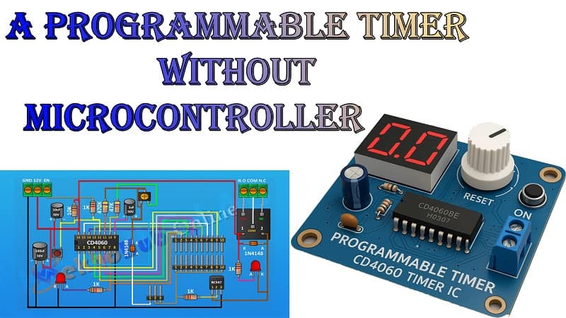

How To Make A Programmable Timer Without Microcontroller.
Have you ever wanted to build a timer that turns a light, fan, or any other device ON or OFF after a set period—without using any microcontroller like Arduino or PIC? This tutorial will teach you how to create a dependable programmable timer using common parts like the CD4060 IC, a few resistors, capacitors, and a transistor, regardless of your preference for analog circuits or your lack of experience with electronics.
This comprehensive guide will cover:
How the timer works
Full circuit explanation
How to customize the delay
Where you can use this timer
And how to make it adjustable
What Is a Programmable Timer?
A programmable timer is a device that turns something ON or OFF after a defined time interval. Most people use microcontrollers for this, but here we’ll show you how to use logic ICs and simple components to achieve the same functionality. This project is ideal for beginners, DIYers, and even professional applications where simplicity and reliability matter.
Materials for the Project
- 1X CD4060 Timer IC
- 1X BC547 Transistor
- 2X 1N4148 Diodes
- 1x Push Button
- 2x LEDS
- 1 x 10k Trimpot
- 4x 1k Resistors
- 1X 10K Resistor
- 1X 47K Resistor
- 1X 470K Resistor
- 1X 1uF Capacitor
- 1X 10uF Capacitor
- 1X 100uF Capacitor
- 1x 12V Relay
- 1x 2-Pin Male Header
- 2x 10-Pin Male Headers
- 2x 3-Pin Terminal Blocks
- JUMPER WIRES
⚙️ Understanding the CD4060 Timer IC
The CD4060 is a 14-stage binary ripple counter with an internal oscillator, meaning it can count time based on the charge and discharge of a capacitor. It’s like having a tiny clock in a chip. You control the timing by choosing the right resistor-capacitor (RC) combination.
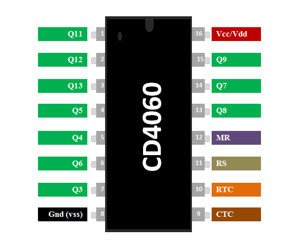
Key pins:
Pin 16: Vcc (Power +)
Pin 8: GND
Pins 9, 10, 11: Connected to RC components for the oscillator
Pin 12: Reset (Must be LOW to enable timer)
Pins 1–7, 13, 14, 15: Output pins (different time delays)
Pin 3 (Q13): Offers a long time delay (ideal for timers)
Download Circuit Diagram

How the Circuit Works
Here’s the step-by-step working of our programmable timer:
Oscillator Setup:
You connect resistors and a capacitor to pins 9, 10, and 11.
This setup creates an internal clock signal.
Counting Time:
The IC counts how many clock pulses have occurred.
The time it takes to reach the output depends on the RC values.
Triggering Output:
After the set time, pin 3 (Q13) goes HIGH.
This signal turns ON the transistor, which can power a relay or LED.
Controlling a Load:
The transistor acts like a switch.
When turned ON, it allows current to flow through a relay or light.
Adjusting the Time:
By changing resistor or capacitor values—or using a potentiometer—you can adjust how long the timer waits before triggering.
Timing Table (Approximate Values)
| R (Ω) | C (µF) | Output Delay (Pin 3 – Q13) |
|---|---|---|
| 1MΩ | 10 µF | ~1.5–2 minutes |
| 1MΩ | 100 µF | ~15–20 minutes |
| 1MΩ | 470 µF | ~1 hour |
| 1MΩ + POT | 470 µF | Up to 2 hours (adjustable) |
Use a potentiometer to fine-tune the timing dynamically.
Applications of This Timer Circuit
This timer can be used in several practical situations:
Battery Charger Cutoff – Turn off the charger after a fixed time.
Auto-Off Light Timer – Switch OFF garden or bathroom lights after minutes.
Appliance Delay Starter – Start heavy machines after a delay.
Plant Watering Systems – Open solenoid valves for a fixed time.
Darkroom Timer – Ideal for photography-related timing tasks.
Add-On Features (Optional)
Manual Reset Button: Connect a push button to pin 12 for restarting the timer.
Multiple Delays: Use selector switches to swap different capacitors.
Visual Feedback: Add an LED on pin 3 for clear status indication.
CD4017 with CD4060: For sequential multi-device timing.
✅ Pros and Cons
✅ Pros:
No code, no microcontroller
Low cost and beginner-friendly
Wide timing range (seconds to hours)
Very stable timing behavior
❌ Cons:
Delay not extremely accurate (not to the second)
No digital display
Limited programmability compared to MCU
Final Thoughts
Creating a programmable timer without a microcontroller is not only possible—it’s also practical, affordable, and reliable. The CD4060 IC is a powerhouse when it comes to time-based applications. Whether you’re building a DIY smart home gadget or just exploring basic electronics, this timer circuit is a great starting point.