

How to Make an Arduino-Based Volt-Ampere Meter DIY Digital Voltage & Current Monitor
In the world of electronics, measuring voltage and current is critical for debugging, testing, and monitoring power supply circuits. Whether you’re powering an LED, building a battery charger, or designing a solar system, you’ll always need a reliable way to measure voltage and current in real time.
So why not build your own?
In this detailed tutorial, you’ll learn how to create a fully functional volt-ampere meter using Arduino. We’ll guide you through every step—from understanding the circuit to writing the code and calibrating the readings.
Only an Arduino, a shunt resistor, and a voltage divider—no sophisticated equipment or expensive parts. Let’s get started.
Table of Contents
Introduction
A volt-ampere (VA) meter is a dual-function meter that simultaneously displays voltage (in volts) and current (in amperes). While commercial VA meters are widely available, building your own offers more flexibility and customization.
By using an Arduino, you can measure:
Voltage using a voltage divider network.
Currently using a shunt resistor and measuring the voltage drop across it.
You’ll also be able to display the readings on the serial monitor or LCD display and even log the data if needed.
Overview
Platform: Arduino UNO/Nano
Voltage Range: 0V to 25V (adjustable via resistor divider)
Current Range: Up to 5A (depending on shunt resistor)
Display: Serial Monitor / 16×2 LCD (optional)
Power Supply: USB or 9V battery
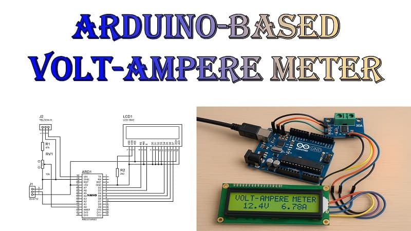
Materials for the Project
- 1x ARDUINO NANO
- 1x 16X2 LCD
- 1x ACS712 (30A) MODULE
- 1x 10K TRIMPOT
- 1X 2K RESISTOR
- 1X 47K RESISTOR
- 2X 2-PIN TERMINAL BLOCKS
- 1X PERF BOARD
- JUMPER WIRES
Download Circuit Diagram

How It Works
⚡ Measuring Voltage
Arduino’s analog pins can read 0–5V.
A voltage divider scales down higher input voltage to a safe 0–5V range.
Formula used:
Measuring Current
A shunt resistor is placed in series with the load.
As current flows, a small voltage develops across the resistor.
Arduino reads this tiny voltage and calculates current using
I = Vshunt / Rshunt
Note: Because voltage across the shunt resistor is very low (millivolts), precision is key.
Calibrate Voltage:
Apply a known voltage (e.g., 12V).
Measure it with a multimeter.
Compare with the Arduino value.
Adjust R1/R2 if needed.
Calibrate Current:
Pass known current through load (e.g., 1A).
Measure voltage across shunt resistor with multimeter.
Ensure Arduino reads it correctly.
Adjust theshuntResistorvalue in the code for accuracy.
Optional: Adding a 16×2 LCD Display.
Wiring:
SDA -> A4 (on UNO)
SCL -> A5
VCC -> 5V
GND -> GND
️ Applications
Battery Monitoring
Power Supply Testing
Solar Panel Output Meter
DIY Electric Vehicle Dash
Lab Bench Power Tool
Data Logging for IoT
✅ Final Thoughts
Building your own Arduino-based volt-ampere meter is a rewarding project that deepens your understanding of analog sensing and real-world power measurements. It’s more than just a DIY tool—it’s an essential learning experience for every electronics enthusiast.