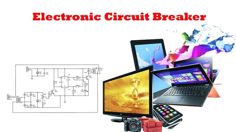
How To Make an Electronic Circuit Breaker
[Sekhohub.online]
Introduction:
An electronic circuit breaker is a smart protective device that automatically disconnects the power when the load exceeds a certain limit. Unlike mechanical breakers, this one uses electronic components like transistors, 555 timer ICs, relays, and current sensors to do the job faster and more reliably.
This project is perfect for:
DIY electronics learners
Overcurrent protection in power supplies
Learning about relay switching and current sensing
Materials for the Project
- 1x 555 TIMER IC
- 2x BC547 TRANSISTORS
- 1x PUSH BUTTON
- 5x 1N4007 DIODES
- 1x LED
- 1x 10K VARIABLE RESISTOR
- 2x 1K RESISTORS
- 4x 10K RESISTORS
- 1x 0.1uF CAPACITOR
- 1x 47uF CAPACITOR
- 1x 100uF CAPACITOR
- 1x CURRENT TRANSFORMER
- 1x 12V RELAY
- 2x 2-PIN TERMINAL BLOCKS
- VERO BOARD
- JUMPER WIRES
Download Circuit Diagram
Circuit Diagram
Conclusion
Creating your own electronic circuit breaker is both fun and educational. It teaches you about overcurrent protection, MOSFET switching, and sensor interfacing. Try this circuit and add your own tweaks to make it even smarter!
For more DIY electronics circuits and tutorials, keep visiting SekhoHub.online—Pakistan’s growing platform for electronics learners and makers.


