Arduino Electronic Component Tester with 16×2 LCD | DIY Project
[Sekhohub.online]
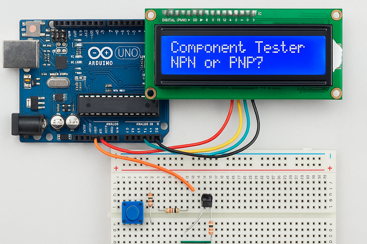
Build an Arduino-based electronic component tester to identify resistors, capacitors, diodes, and transistors. Display results on a 16×2 LCD. A perfect DIY project for electronics hobbyists and repair technicians.
Introduction
Testing individual electronic components is crucial for both designing circuits and troubleshooting faults. In this project, we’ll build a DIY electronic component tester using Arduino Uno and a 16×2 LCD display. This tester can identify and measure resistors, capacitors, diodes, transistors, and more!
Materials for the Project
- 1x ARDUINO UNO
- 1x 16X2 LCD
- 1x PUSH BUTTON
- 1x 10K VARIABLE RESISTOR
- 3x 680 OHM RESISTORS
- 3x 470K RESISTORS
- 1x nF CAPACITOR
- MALE HEADERS
- 1x 3-PIN TERMINAL BLOCK
- FEMALE HEADERS
- VERO BOARD
- JUMPER WIRES
- USB Cable + 5V Power Supply
Download Circuit Diagram
Circuit Diagram
Download Arduino Code
Arduino Code
⚙️ Working Principle
This Arduino-based tester works by:
Sending known voltages/currents through the component
Measuring response (voltage drop, time constants, etc.)
Identifying the type of component and calculating values (like resistance or capacitance)
Results are displayed in real-time on the 16×2 LCD screen.
Video Tutorial
Features
Tests Resistors, Capacitors, Diodes, NPN/PNP Transistors
Easy to build with common parts
Can be upgraded with rotary encoders or TFT LCD
Ideal for electronics learners, repair technicians, or hobbyists
Expandability Ideas
Add support for MOSFETs, Zener Diodes, or inductors.
Upgrade LCD to I2C version for fewer pins
Add auto power-off feature or battery supply