

Introduction
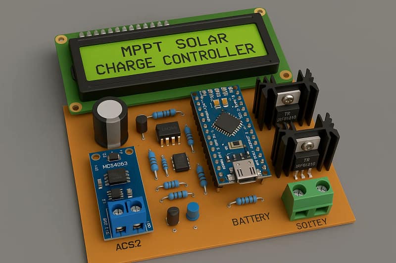
In this tutorial, we will show you how to make an advanced MPPT solar charge controller that accepts a high-voltage solar panel input (up to 80V) and charges 12V or 24V batteries efficiently. MPPT (Maximum Power Point Tracking) technology increases the efficiency of solar charging by extracting the maximum power available from the panel. This controller uses an Arduino Nano, a 16×2 LCD, an ACS712 current sensor, an MC34063 boost/buck IC, an LM358 op-amp, and IRFB4310 MOSFETs for switching.
Materials for the Project
- 1x Arduino Nano
- 1x 16×2 LCD
- 3x Push Buttons
- 2 x ACS712 Sensor
- 1 x MC34063 IC
- 1X LM358 IC
- 4X IRFB4310 MOSFETs
- 1X MJE13005 Transistor
- 1X BC547 Transistor
- 1 x 1N5809 Diode
- 1 x 1N4751 Diode
- 2 x MBR20100CT Diodes
- 1 x PC817 Optocoupler
- 1 x 330 uH Inductor
- 1 x uH Inductor
- 1 x 1n Capacitor
- 1 x 100u 50V Capacitor
- 4 x 1000u 100V Capacitors
- 2 x 5k Trimpot
- 1 x 1R Resistor
- 2 x 100R Resistors
- 5 x 10k Resistors
- 1 x 3.3k Resistor
- 3 x 47k Resistors
- 3 x 220k Resistors
- 1 x 1k Resistor
- 2 x 2 Pin Terminal Block
- jumper wires
Download Circuit Diagram

Circuit Diagram Overview
Sections:
Solar Input Stage (Up to 80V):
Uses voltage divider for safe Arduino sensing
Current monitored via ACS712
MPPT Control Stage:
Arduino runs MPPT algorithm and controls PWM
MOSFET switching with IRFB4310
Uses MC34063 or custom buck converter stage
Battery Charging Stage:
Controlled switching to charge 12V or 24V batteries
LM358 for voltage level comparison (optional cutoff logic)
Display Section:
I2C LCD for real-time data: Solar V/I, Battery V, Power
Conclusion
This high-voltage MPPT solar charge controller project is ideal for off-grid or hybrid solar systems. It offers high efficiency, safety, and expandability, charging 12V or 24V batteries from 80V solar input. You can customize the code, battery voltage range, or display features as needed.