
he ESP32 PLC is a powerful, low-cost automation controller designed for industrial and DIY projects. With the ESP32 PLC, you can control motors, sensors, and relays using Wi-Fi or Bluetooth. This ESP32 PLC supports multiple inputs and outputs, making it ideal for smart factory systems. Whether you’re building home automation or industrial monitoring, the ESP32 PLC offers reliability and easy programming. Integrate the ESP32 PLC with Modbus or MQTT protocols for seamless communication.
The ESP32 PLC is compatible with Arduino IDE and MicroPython, allowing flexible coding. Using ESP32 PLC modules, you can create scalable and energy-efficient systems. The ESP32 PLC ensures real-time control and IoT connectivity for engineers and hobbyists alike. Experience advanced automation with the ESP32 PLC and simplify your industrial projects.
Video Tutorial
Introduction
In modern industrial automation, ESP32 PLC systems are gaining attention for their versatility, cost-effectiveness, and ease of customization. Traditional PLCs are reliable but often expensive and closed-source, limiting their flexibility for educational and small-scale industrial applications. The ESP32-based programmable logic controller bridges this gap by combining the powerful dual-core ESP32 microcontroller with the robustness of industrial control logic.
This integration allows engineers, hobbyists, and developers to design smart automation systems with built-in Wi-Fi and Bluetooth capabilities, making remote monitoring and IoT connectivity easier than ever. With its modular design, support for multiple I/O configurations, and compatibility with standard PLC programming methods, the ESP32 controller offers a practical entry point into both industrial control and IoT-based automation.
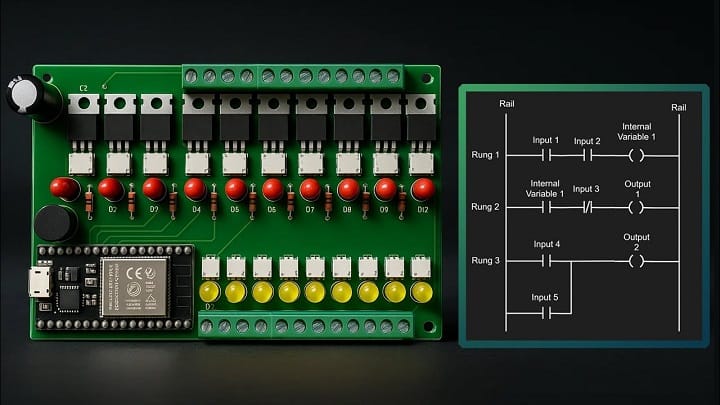
Materials for the Project
- 10 × PC817 Optocoupler
- 10 × MOC3021 Optocoupler
- 10 × BT136 TRIAC
- 10x Red LED
- 10x Yellow LED
- 1x 1000uF 50V Capacitor
- 20 × 100Ω Resistor
- 10 × 220Ω Resistors
- 10 × 1 kΩ Resistors
- 12x 2-Pin Terminal Blocks
- Jumper Wires
Useful Tools
| Tool | Quantity | Purpose / Notes | Click & Buy |
|---|---|---|---|
| Soldering Iron Kit | 1 | For making permanent connections | Click & Buy |
| Solder Wire (60/40, 0.8mm) | 1 | Electrical soldering | Click & Buy |
| Wire Stripper & Cutter | 1 | Stripping jumper wires | Click & Buy |
| Mini Screwdriver Set | 1 | For module and relay terminal screws | Click & Buy |
| Multimeter | 1 | Testing voltages and continuity | Click & Buy |
| Hot Glue Gun (optional) | 1 | Securing components in place | Click & Buy |
| Small Pliers | 1 | Holding and bending wires | Click & Buy |
| Heat Shrink Tubing Set | 1 | Insulating exposed wires | Click & Buy |
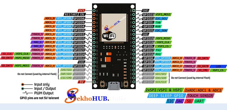
ESP32 Pinout.
| Pin | Type | Typical Use | Notes |
|---|---|---|---|
| 3V3 | Power | 3.3V supply to sensors, modules | Do not exceed 3.3V |
| GND | Power | Ground | Connect to all circuits for reference |
| EN (RST) | Control | Reset | Pull low to reset ESP32 |
| VIN | Power | Input voltage (5–12V) | Feeds internal regulator |
| GPIO 0 | Digital | Boot mode / general purpose | LOW at boot = flash mode |
| GPIO 1 (TX0) | UART | Serial TX | Avoid using for programming |
| GPIO 3 (RX0) | UART | Serial RX | Avoid using for programming |
| GPIO 2 | Digital | LED / general I/O | Has internal pull-up |
| GPIO 4 | Digital | Relay / sensor | Safe for outputs |
| GPIO 5 | Digital | Relay / LED | Standard digital I/O |
| GPIO 12 | Digital | SPI / output | Boot-sensitive |
| GPIO 13 | Digital | SPI / output | Can drive LEDs or relays |
| GPIO 14 | Digital | SPI / output | Safe for outputs |
| GPIO 15 | Digital | SPI / input | Boot-sensitive |
| GPIO 16, 17 | Digital | UART / output | Safe for general I/O |
| GPIO 18–23 | Digital | SPI / I2C / output | Multi-purpose, can drive relays |
| GPIO 25–27 | Digital / ADC / DAC | PWM / analog output | DAC pins for analog signals |
| GPIO 32–39 | Digital / ADC | Sensor inputs / analog | 3.3V max, input only for 34–39 |
| VP (GPIO 36), VN (GPIO 39) | Analog | ADC channels | Input-only, no pull-up |
| SDIO / SPI Pins | Digital | SD card / SPI | Shared functions with other GPIOs |
| SCL / SDA | I2C | Sensor communication | Default I2C pins (GPIO 22 = SCL, GPIO 21 = SDA) |
Notes:
PWM: Any GPIO except input-only pins can be used for PWM (relay control, LEDs).
ADC: GPIOs 32–39 for analog sensors.
Boot-sensitive Pins: GPIO 0, 2, 12, 15 – avoid driving high during boot unless intentional.
Relay/Output Control: Use GPIO 4, 5, 16, 17 for safe switching.
Voltage Limits: ESP32 GPIO pins are 3.3V max. Never exceed.
⚙️How to Program:
You can program the ESP32 in two ways:
Option 1: Arduino IDE (Manual Control Logic)
Use digitalWrite() to turn loads ON/OFF based on sensors, timers, etc.
#define RELAY_PIN 23
void setup() {
pinMode(RELAY_PIN, OUTPUT);
}
void loop() {
digitalWrite(RELAY_PIN, HIGH); // Turn ON load
delay(1000);
digitalWrite(RELAY_PIN, LOW); // Turn OFF load
delay(1000);
}
Option 2: OpenPLC for Ladder Programming
Install OpenPLC Editor on your PC
Write ladder logic (NO/NC contacts, coils)
Compile for ESP32 using OpenPLC firmware
Upload via USB or WiFi
✅Advantages of ESP32 PLC with SSR:
Silent operation (no clicks like mechanical relays)
High-speed switching
Durable (no moving parts)
Compact & reliable
WiFi and Bluetooth support
Suitable for industrial-grade projects
Applications:
Smart home automation
Industrial process control
IoT systems
Timed irrigation or motor control
Energy-efficient automation systems
Download Gerber Files
Gerber Files