

Introduction to LED Chaser with ATTINY85 & 74HC595 IC.
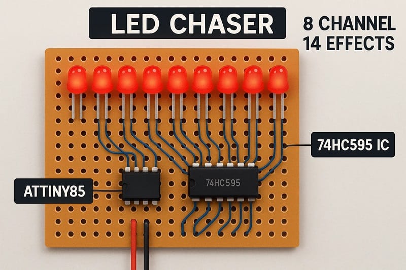
An LED chaser is a visual effect where LEDs light up in a sequence, creating a “chasing” effect. It’s a popular project for learning microcontrollers and shift registers, as it involves basic programming and electronics principles. In this project, we’ll use an ATTINY85 microcontroller and a 74HC595 shift register to create an 8-channel LED chaser with 14 different effects.
The ATTINY85 is a small, low-power microcontroller that offers just enough pins to control an LED chaser, while the 74HC595 shift register helps extend the number of LEDs that can be controlled by shifting bits of data. By using this combination, we can control 8 LEDs with just a few pins on the ATTINY85.
Why ATTINY85 & 74HC595?
ATTINY85: This microcontroller has only 5 I/O pins, but it’s capable of controlling multiple devices using shift registers. It’s a small, low-cost, and power-efficient choice for small embedded projects.
74HC595 Shift Register: This IC allows serial data to be shifted out to multiple outputs. It can control 8 LEDs using only 3 pins from the ATTINY85, freeing up the remaining pins for other functions or additional shift registers.
By chaining two 74HC595 shift registers, we can create a flexible and scalable LED chaser with 8 LEDs (per register) and multiple effects. The 14 different effects will add variety and complexity to the visual pattern.
Project Objective:
The goal is to program the ATTINY85 to control the LEDs using the 74HC595 shift register, creating different chasing patterns and effects. You’ll learn how to manipulate the shift register, control multiple LEDs, and write different lighting effects in the code.
In the next sections, we’ll dive into the hardware setup and software implementation, followed by a breakdown of different effects you can achieve.
Materials for the Project
- 1 X ATTINY85
- 1x 74HC595 IC
- 8X LED
- 8X 100 Ohm Resistors
- 1X 10K Resistors
- 1x Push Button
- 1x 10K TRIMPOT
- 1x 2-Pin Terminal Blocks
- Arduino UNO
- Remote Control
- 1X PERF BOARD
- JUMPER WIRES
Download Circuit Diagram


Wiring Setup:
ATTINY85 Pins:
Pin 1 (PB5) → Data (DS) of 74HC595
Pin 2 (PB3) → Clock (SH_CP) of 74HC595
Pin 3 (PB4) → Latch (ST_CP) of 74HC595
74HC595 Connections:
DS (Data Pin) → Connect to the PB5 of ATTINY85
SH_CP (Clock Pin) → Connect to PB3 of ATTINY85
ST_CP (Latch Pin) → Connect to PB4 of ATTINY85
QH’ (Serial Out Pin) → Connect to DS of second 74HC595 (for cascading)
VCC → Connect to 5V
GND → Connect to Ground
Q0 to Q7 (Outputs) → Connect to LEDs (through current-limiting resistors)
LEDs:
Use 8 LEDs connected to the output pins of the 74HC595 (Q0 to Q7).