
How to Make LED Dimmer Using a 555 Timer IC & IRFP3205 MOSFET
[Sekhohub.online]

Introduction
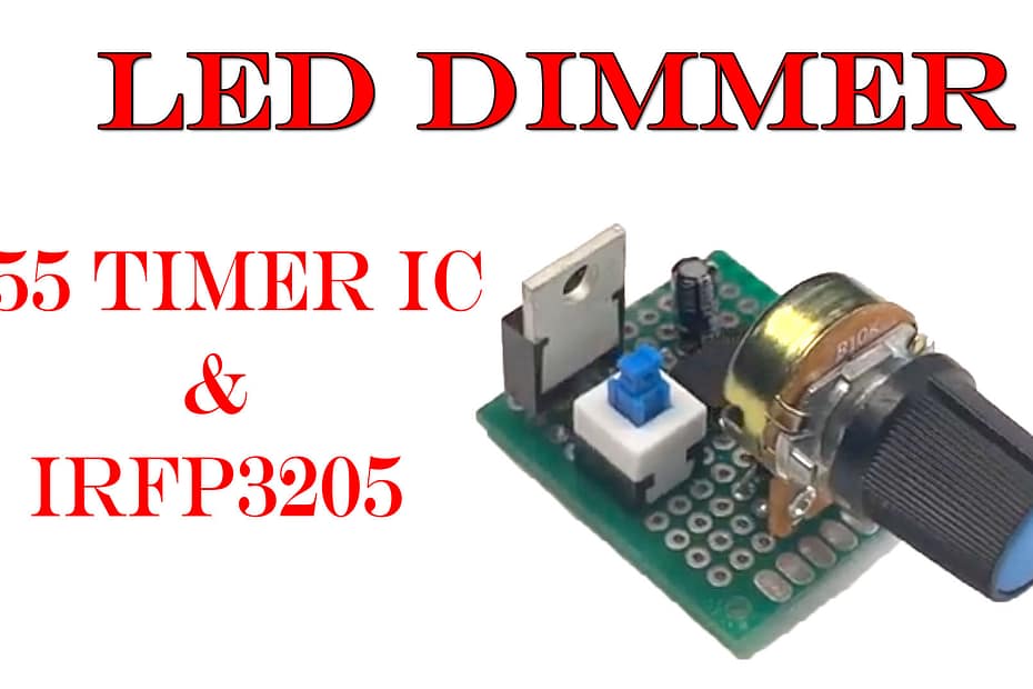
An LED dimmer circuit allows you to adjust the brightness of an LED light. In this project, we’ll build a simple but powerful PWM-based LED dimmer using a 555 Timer IC, a powerful IRFP3205 MOSFET, and a 50k variable resistor.
Materials for the Project
1- 1X 555 TIMER IC
2- 1X IRFP 3205 MOSFET
3- 1X 50 K OHM VARIABLE RESISTORS
4- 2X 1 K OHM RESISTORS
5- 2X 10 K OHM RESISTORS
3- 1X 0.1uF CAPACITOR
4- 1X 1N4007 DIODES
5- 2X 2PIN TERMINAL BLOCKS
6- 1X VERO BOARD
7- SOME WIRES
Download Circuit Diagram

Circuit Diagram
Working Principle
This LED dimmer circuit uses the 555 timer in astable mode to generate a PWM (Pulse Width Modulation) signal. By turning the 50k variable resistor, the duty cycle of the PWM signal changes. This signal drives the IRFP3205 MOSFET, which controls the power to the LEDs.
Higher Duty Cycle = Brighter LED
Lower Duty Cycle = Dimmer LED
Circuit Explanation
Pin 1 (GND) → Connect to negative (–) of the power supply
Pin 8 (VCC) → Connect to positive (+12V)
Pin 3 (Output) → Connect to gate of IRFP3205
Pin 2 & 6 (Trigger & Threshold) → Connected together
Pin 4 (Reset) → Connect to VCC
Pin 5 (Control Voltage) → Optional; connect a 10 nF capacitor to ground
IRFP3205 Source → GND
IRFP3205 Drain → LED negative terminal
LED Positive Terminal → +12V power
Testing and Results
When you power the circuit, the LED lights up.
Rotating the 50k pot changes the LED brightness.
The IRFP3205 handles high current easily, making this ideal for long LED strips too.
Advantages
Simple and low-cost circuit.
Works with high-power LEDs.
Protects LED from overcurrent by PWM.
IRFP3205 can handle up to 110 A peak current.
⚠️ Precautions
Use a proper heatsink on the MOSFET if driving high-current LEDs.
Ensure the power supply is regulated at 12V DC.
Don’t short-circuit the output side.