
How to Make an LED Sign Board Using a 555 Timer & a 74HC595 Shift Register IC.
An LED Sign Board is a practical electronic display used to present text, symbols, or animations for information and advertising purposes. It is widely applied in shops, offices, schools, and public spaces because of its low power consumption and long life. Using LED display board, designers can create eye-catching visual messages that remain clearly visible even in bright environments.
Modern systems often integrate controllers to manage scrolling effects and brightness, making them suitable for both indoor and outdoor use. With simple circuitry and flexible programming, digital LED sign board projects are popular among beginners and professionals. This technology also supports programmable LED display designs, allowing easy updates and creative layouts for various display needs.
Overview
The LED Sign Board operates by driving multiple LEDs in a matrix or segment arrangement to form readable characters and patterns. A control unit manages timing, data flow, and brightness to ensure smooth visual output. Using an LED message display, users can show static text or scrolling information based on requirements.
These systems are efficient, reliable, and adaptable for different environments. Advanced designs may include wireless control or memory storage for preset messages, improving usability. With a well-planned circuit and proper power management, an electronic sign board can function continuously with minimal maintenance, making it a cost-effective solution for information display.
Materials for the Project
Below is the complete list of components used to build the LED Sign Board circuit. All parts are commonly available and suitable for beginner to intermediate DIY electronics projects.
| Component | Quantity | Purpose |
|---|---|---|
| 74HC595 Shift Register IC | 1 | Expands output pins to control multiple LEDs efficiently |
| 555 Timer IC | 1 | Generates clock pulses for LED shifting and timing control |
| 7805 Voltage Regulator IC | 1 | Provides regulated 5V DC supply to the circuit |
| BD139 Transistor | 1 | Drives higher current loads safely |
| BC547 Transistors | 7 | Used as LED drivers and switching elements |
| 1N4007 Diodes | 4 | Reverse polarity and back-EMF protection |
| LEDs | 4 | Visual display elements for the sign board |
| 10 kΩ Variable Resistor | 1 | Adjusts speed or brightness of LED effects |
| 1 kΩ Resistors | 9 | Current limiting and base resistors |
| 10 kΩ Resistors | 5 | Biasing and pull-down purposes |
| 0.1 µF Capacitors (104) | 2 | Noise filtering and signal stability |
| 10 µF Capacitor | 1 | Timing and smoothing |
| 47 µF Capacitor | 1 | Voltage stabilization |
| 100 µF Capacitor | 1 | Power supply filtering |
| Vero Board | 1 | Permanent circuit assembly |
| Jumper Wires | As required | Interconnections between components |
Working Principle
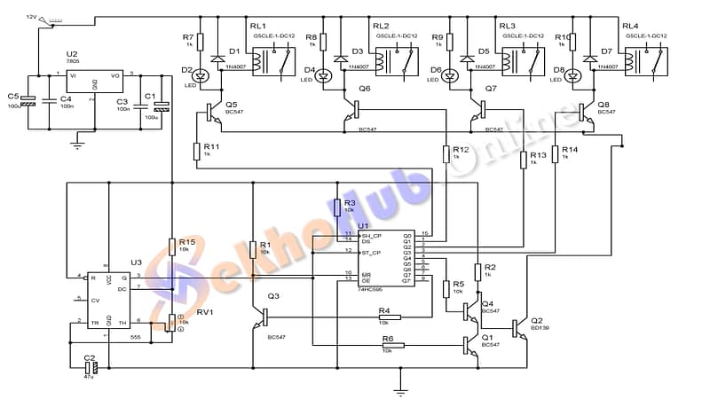
The 555 timer is configured in astable mode to generate clock pulses.
These pulses are fed to the 74HC595, which shifts the LED display pattern one step at a time.
You can daisy-chain multiple 74HC595 ICs to expand the LED display up to 64 or more LEDs.
74HC595 Pinout
| Pin | Name | Function |
|---|---|---|
| 1-7, 15 | Q0–Q7 | Parallel output to LEDs |
| 8 | GND | Ground |
| 9 | Q7’ | Serial Out (for chaining) |
| 10 | MR | Master Reset (active LOW) |
| 11 | SH_CP | Shift Clock (from 555 output) |
| 12 | ST_CP | Storage Clock (latch) |
| 13 | OE | Output Enable (active LOW) |
| 14 | DS | Serial Data Input |
| 16 | VCC | Power supply (5V) |
Download Circuit Diagram
How the LED Pattern Works
Each time the 555 sends a clock pulse, the shift register moves bits from DS into the output.
This shifts the LED pattern left or right.
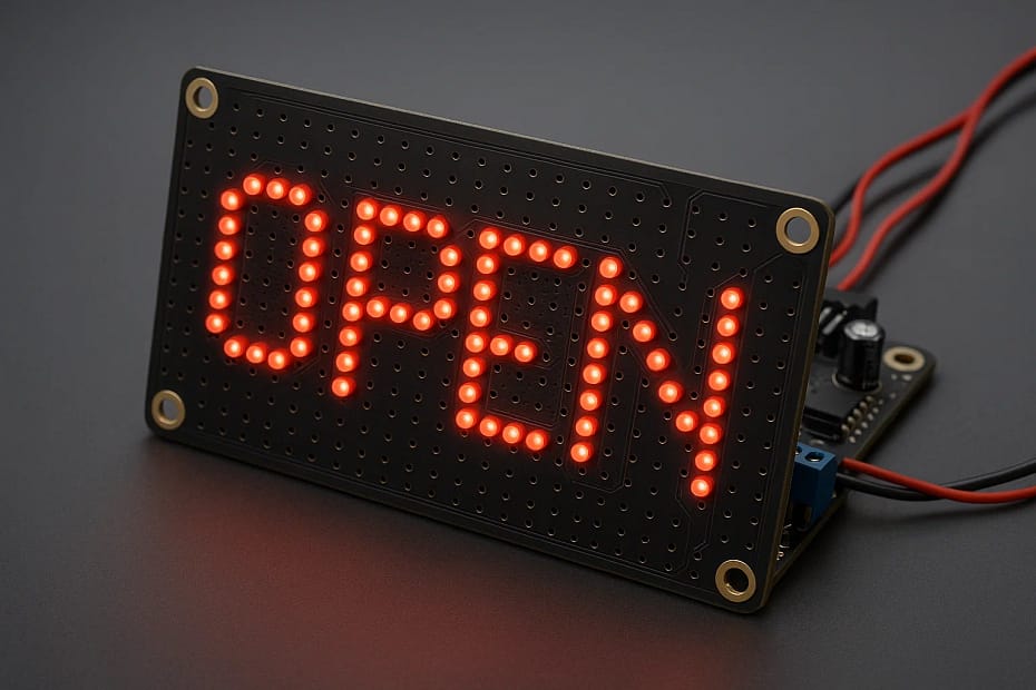
By chaining multiple 74HC595s, you can scroll a name or logo like “OPEN” or “SALE.”
Where to Use It?
LED name boards (“WELCOME,” “OPEN,” etc.)
Low-cost electronic signage
Decorative LED chasers
School/college mini projects
Conclusion
The LED Sign Board project demonstrates how basic electronic components can be combined to create an effective and reusable display system. By using ICs like the 555 timer and 74HC595 shift register, the circuit achieves controlled LED switching with stable timing and low power consumption. This project is suitable for learning display control, timing circuits, and transistor switching techniques. With proper assembly on a vero board and correct power regulation, the LED sign board operates reliably for long durations. It also provides a strong foundation for expanding into scrolling text, larger LED matrices, or microcontroller-based display systems.