
Introduction
If you’re looking to build a powerful and budget-friendly stereo amplifier, the LA4440 IC is one of the best choices for hobbyists and electronics enthusiasts. It’s a versatile dual-channel audio amplifier IC capable of delivering 6W to 20W per channel, depending on your supply and configuration.
In this guide, we’ll walk you through how to make a stereo amplifier using the LA4440 IC, explain the working principle, provide a circuit diagram, and list all necessary components. Whether you’re upgrading an old speaker system or building a new DIY audio setup, this project is perfect for anyone looking to experience clear and powerful stereo sound with minimal components.
Let’s get started and build your own audio amplifier!
Materials for the Project
1- 1X LA 4440 IC
2- 1X HEAT SINK
3- 5X 100UF 50V CAPACITOR
4- 2X 470UF 50V CAPACITOR
5- 1X 1000UF 35V CAPACITOR
6- 2X 4.7UF 50V CAPACITOR
7- 2X 0.1 µF NON-POLAR CAPACITOR
8- 2X 2.2KΩ RESISTOR
9- VERO BOARD
10- JUMPER WIRES
Download Circuit Diagram
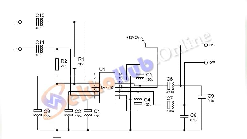
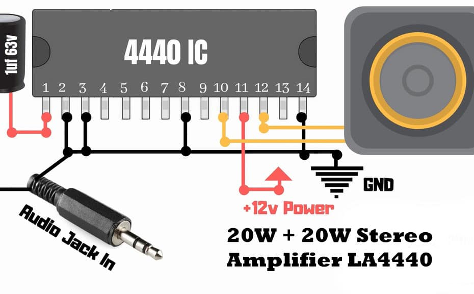
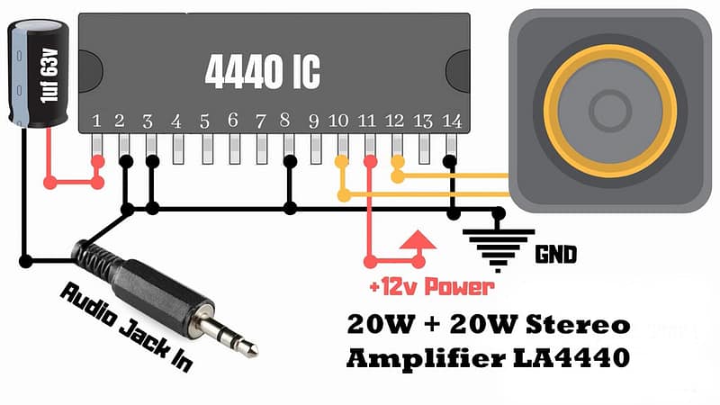
Circuit Diagram
LA4440 IC Pin Configuration (14-Pin Dual Channel Audio Amplifier)
The LA4440 is a 14-pin SIP (Single In-line Package) audio amplifier IC, commonly used for stereo or bridge audio amplifier circuits.
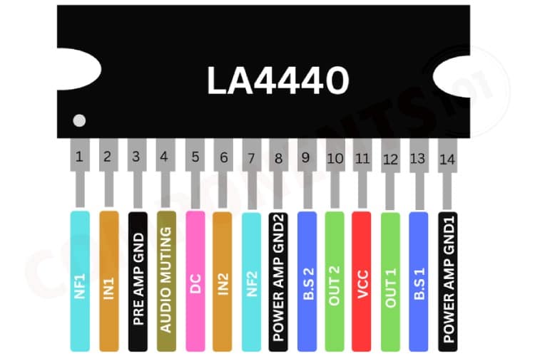
LA4440 IC Pin Configuration.
| Pin No. | Name | Function |
|---|---|---|
| 1 | Non-Inverting Input 1 | Audio input for Channel 1 |
| 2 | Inverting Input 1 | Connected to feedback resistor/capacitor |
| 3 | Bootstrap 1 | Frequency compensation (connect capacitor) |
| 4 | Ripple Filter | Reduces power supply ripple noise |
| 5 | Output 1 | Output of Channel 1 (connect to speaker) |
| 6 | VCC (Power Supply) | Connect +12V to +15V DC |
| 7 | Ground (GND) | Common ground |
| 8 | Output 2 | Output of Channel 2 (connect to speaker) |
| 9 | Bootstrap 2 | Frequency compensation for Channel 2 |
| 10 | Inverting Input 2 | Connected to feedback circuit |
| 11 | Non-Inverting Input 2 | Audio input for Channel 2 |
| 12 | Standby Switch | Pull low to disable (optional, tie to ground if unused) |
| 13 | Muting Switch | Pull low to mute output (optional, tie to ground if unused) |
| 14 | NC (Not Connected) | Not used |
Notes:
Pin 6 (VCC): Use regulated 12V–15V DC.
Pins 5 and 8: Connect speakers (via capacitors if needed).
Pins 12 & 13: Tie to GND with a 10 kΩ resistor if not using standby/mute features.
⚙️ Working Explanation
The LA4440 is a dual power amplifier IC, internally consisting of two channels. You can use it in:
Stereo Mode: Each channel drives a speaker independently.
Bridge Mode: Both channels combine for higher power output to a single speaker.
In stereo mode:
The audio input is split and fed into each channel via decoupling capacitors.
Capacitors filter out noise and stabilize the signal.
A power supply of 12V–15V DC powers the IC.
The output from each channel drives a speaker for left/right stereo sound.
Make sure to attach a heat sink to prevent overheating during high-volume playback.
Applications
DIY Home Stereo Systems
Car Audio Amplifiers
Mini Home Theater Projects
Upgrading Old Speakers
Audio Testing Setups
✅ Advantages
Simple and low-cost setup
Good sound quality for home use
Dual- or bridge-mode flexibility
Works with 4Ω or 8Ω speakers
Easily available components
⚠️ Tips and Precautions
Use a proper heat sink with LA4440 IC
Don’t exceed the voltage rating (max 18V)
Use filter capacitors near the power supply
Ensure good soldering to avoid noise/hiss
Conclusion
Making a stereo amplifier using the LA4440 IC is a fun and rewarding project. It delivers surprisingly good sound quality and volume for such a compact circuit. Whether you’re new to electronics or want a simple, budget-friendly amplifier, the LA4440 won’t disappoint.