

How to Use a Multiplexer with Arduino to Expand Inputs & Outputs
Introduction.
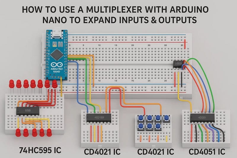
Do you have more sensors or devices than your Arduino has input/output pins? Don’t worry! With a multiplexer (MUX), you can expand your Arduino’s I/O capability without changing the microcontroller. In this guide, you’ll learn what a multiplexer is, how to connect it, and how to control it using Arduino code.
Materials for the Project
- 1x Arduino Nano
- 2x 74HC595 IC
- 2x CD4021 IC
- 2x CD4051 IC
- 16x 10k Resistors
- 6x 16-Pin IC Bases
- Female And Male Headers
- JUMPER WIRES
What is a multiplexer?
A multiplexer (or MUX) is a digital switch that allows you to select one of many inputs/outputs using a few control pins. Think of it as a rotary switch controlled by the Arduino.
Common Multiplexer ICs:
| IC Name | Channels | Type |
|---|---|---|
| 74HC595 IC | Analog/Digital | |
| CD4021 IC | Analog/Digital | |
| CD4051 IC | Analog/Digital |
Download Circuit Diagram


Required Components
Arduino Uno (or any compatible board)
74HC595 IC andCD4051 IC Multiplexer
Potentiometers or sensors (for inputs)
LEDs or relays (for outputs)
Jumper wires
Breadboard
Power supply (5V)
Why Use a Multiplexer?
✅ Save Arduino pins
✅ Read from or write to many devices
✅ Cost-effective I/O expansion
✅ Supports both analog and digital signals
Applications
Multiple sensor reading (temperature, light, etc.)
LED matrix control
Keypad reading
Robotics and automation systems
Audio or analog signal routing
Conclusion
Using a multiplexer with Arduino is a powerful way to handle more I/O devices while using fewer pins. Whether you’re building a smart home system, a robot, or a multi-sensor data logger, MUX chips can help you scale easily.