
The transistor is a simple component that you can use to build a lot of fun projects. You’ll learn how transistors work in this hands-on guide so you can use them in your next circuit.
And once you understand the fundamentals, it’s actually not that hard. Here, I’ll concentrate on the BJT and the MOSFET, the two most prevalent transistors.

The transistor is like a switch on an electronic device. It can turn on and off a current. Thinking of the transistor as a relay with no moving parts is a straightforward approach. In that it can be used to turn something ON or OFF, a transistor is similar to a relay.
A transistor, on the other hand, can also be partially turned on, which is useful for making amplifiers.
How Transistors Work (BJT)
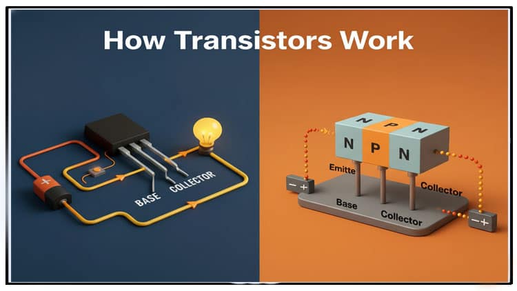
First, let’s look at the standard NPN transistor. It’s a Bipolar Junction Transistor (BJT) and has three legs:
- Base (b)
- Collector (c)
- Emitter (e)

If you turn it ON, current can flow through it from the collector to the emitter. There is no flow of current when it is OFF.
The transistor is OFF in the example circuit below. The Light-Emitting Diode (LED) is also off as a result of the fact that no current can pass through it.

A voltage of about 0.7V is required to be present between the transistor’s base and emitter in order to turn it ON.
The transistor would have been ON if you had a 0.7V battery connected between the base and the emitter.
How do we activate the transistor since most of us do not have a 0.7V battery?
Easy! A transistor’s base-to-emitter section functions similarly to a diode. A diode “grabs” a forward voltage from the voltage that is available. The remaining voltage drops across the resistor when a resistor is added in series.
Thus, adding a resistor will automatically result in approximately 0.7V.
This is how you prevent an LED from exploding by restricting the current flowing through it.
If you also add a pushbutton, you can use a button to turn the transistor on and off and the LED as a result:

Choosing Values for the Parts.
There is one more thing you need to know about how transistors work before you can choose the values of the components:
The transistor activates so that a greater current can flow from the collector to the emitter when current flows from the base to the emitter.

The dimensions of the two currents are connected. The transistor’s gain is the term for this.
This could be around 100 for a general-purpose transistor like the BC547 or 2N3904.
This indicates that if you have 0.1 mA flowing from the base to the emitter, you can have 10 mA flowing from the collector to the emitter, which is 100 times more.
What resistor value do you need for R1 to get 0.1mA flowing ?
There is still 8.3V across the resistor if the battery has 9V and the transistor’s base-to-emitter voltage is 0.7V.
The value of the resistor can be determined using Ohm’s law:


So you need a resistor of 83 kΩ. Although 82 k is not a standard value, it is close enough.
The function of R2 is to restrict the LED’s current. If you were to connect the LED and resistor directly to the 9V battery without the transistor, you can select the value. For example, 1 kΩ should work fine.
How Choose a Transistor.
The most prevalent type of Bipolar Junction Transistors (BJT) is the NPN transistor. But there is another one called a PNP transistor that works the same way, just that all the currents are in the opposite direction.
The most crucial consideration when selecting a transistor is its capacity to sustain current. The Collector Current (IC) refers to this.
The Workings of a MOSFET Transistor.
The MOSFET transistor is another very common type of transistor. It also has three pins:
- Gate (g)
- Source (s)
- Drain (d)

A MOSFET works similar to the BJT transistor, but with one important difference:
In the BJT transistor, the current from base to emitter decides how much current can flow from collector to emitter.
The MOSFET transistor’s drain-to-source current limit is determined by the voltage between the gate and source.
Example: How to activate a MOSFET.
A typical circuit for activating a MOSFET can be found below.

A voltage greater than the threshold voltage of your MOSFET transistor is required between the gate and source to activate it. For example, the BS170 has a gate-source threshold voltage of 2.1V. (This information can be found in the datasheet.)
A MOSFET’s turning off voltage is actually its threshold voltage. Therefore, a voltage slightly higher than that is required to properly activate the transistor.
How much higher depends on how much current you’d like to have flowing (and you’ll find that info in the datasheet). For low-current tasks like turning on an LED, a few volts above the threshold is typically sufficient.
Keep in mind that even if you use a voltage that is high enough to deliver 1A of current, this does not guarantee that you will. It merely indicates that you could, if you so desired, have 1A flowing. But it’s whatever you connect to it that decides the actual current.
Therefore, you are free to go as high as you like provided that you do not exceed the maximum gate-source voltage limit (which is 20V for the BS170).
When you press the button in the example above, the gate is connected to 9V. The transistor is turned on by this.
Choosing the Values of the Parts.
The value of R1 is not important; it should be around 10 k. Its function is to disable the MOSFET (more on that later).
The LED’s brightness is set by R2, which should be 1 k for most LEDs.
Q1 could be any n-channel MOSFET, including BS170, for example.
How Do I Disable a MOSFET?
How to Turn Off a MOSFET Understanding that it also functions somewhat like a capacitor is important. Specifically, the gate-source portion. A voltage that is applied between the gate and the source remains there until it is discharged.MOSFET?

In the previous example, the transistor would not turn off without the resistor (R1). The transistor turns off once more because the resistor provides a pathway for the gate-source capacitor to discharge.
Selecting a MOSFET Transistor.
The example above makes use of an N-channel MOSFET. P-channel MOSFETs function in a similar manner, with the exception that the current flows in the opposite direction, and the gate to source voltage must be negative in order for the device to turn on.
There are tens of thousands of different MOSFETs available. However, BS170 and IRF510 are two common choices if you want to construct the above-mentioned example circuit and require a specific recommendation.
When selecting a MOSFET, there are two things to keep in mind:
- The voltage at which the gate meets the source. To activate the transistor, a voltage greater than this is required.
- The ever-present drain current. This is the maximum amount of current that your transistor can handle.
Depending on the product you’re making, there are additional important parameters to keep in mind. However, that goes beyond the scope of this article. If you keep in mind the two parameters above, you will have a good place to start.
Gate Current of a MOSFET.
Another thing to keep in mind if you want to control a MOSFET from an Arduino or Raspberry Pi is the current that flows into the gate when the transistor is turned on.
A MOSFET’s gate-to-source function is briefly described above.
That means once it’s charged, no more current flows through it. Therefore, there is no current flowing through the gate of a MOSFET when it is on.
However, just like when you charge a capacitor, there is a current when a MOSFET is turned on. There may be a lot of current flowing for a brief period of time.
Add a MOSFET gate resistor to your Arduino or other device to prevent it from drawing too much current:

Most of the time, 1000 suffices for this. Utilize Ohm’s law to assess your particular circumstance.
Why is a transistor necessary?
I frequently get the inquiry, “Why do we require the transistor?” Why not simply connect the resistor and LED to the battery?
A transistor’s advantage is that you can control a much larger current or voltage with a smaller current or voltage.
That’s super useful if you want to control things like motors, high-power LEDs, speakers, relays, and more from a Raspberry Pi/Arduino/microcontroller. At 5V, these boards’ output pins typically only provide a few milliamperes. Therefore, you are unable to control your 110V outdoor patio lights directly from the pin.
You could do it with a relay instead. However, even the relay frequently requires more current than the pin can supply. Therefore, you would require a transistor to control the relay:

However, simpler sensor circuits like the H-Bridge, touch, and light sensor circuits can also benefit from transistors.
Transistors are utilized in nearly every circuit. In fact, it is the most significant electronic component.
Amplifier: The Transistor.
Amplifiers also work because of the transistor. It is possible for it to be anywhere in between “fully on” and “fully off,” as opposed to just having two states, ON and OFF.
That means a small signal with almost no energy can control a transistor to create a much stronger copy of that signal in the collector-emitter (or drain-source) part of the transistor. Thereby, the transistor can amplify small signals.
An easy amplifier for driving a speaker can be found below. The current flowing through the speaker and from the base to the emitter both increase proportionally with the input voltage.
The speaker’s current changes as the input voltage changes, resulting in sound.

To normally bias the transistor, you would add a few more resistors. If you don’t, there will be a lot of distortion. However, that is for a different article.
sekhohub.online has some good tutorials that go over the three basic BJT amplifier setups if you want to learn more about using the transistor as an amplifier.
Questions?
Do you now comprehend how transistors function? Or do you still have questions? Let me know in the comments below.
More Tutorials on Transistors.
How to Make a 2-Channel Relay Module Eays stap
All Components Tester (No MCU) | 9 Proven Checks for Components
Joule Thief Circuit Using a BC547 Transistor and Common Resistors
Automatic Street Night Light Circuit Using LDR