

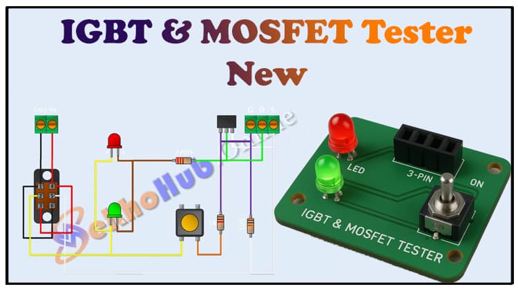
IGBT and MOSFET Tester Circuit | DIY Electronics Project With LEDs
Build a simple IGBT and MOSFET tester circuit using just LEDs, resistors, and a DPDT switch. This IGBT and MOSFET tester guide shows how to check the functionality of your transistors before using them in projects. Learn step-by-step how to make this IGBT and MOSFET tester with minimal components. The IGBT and MOSFET tester uses 2 LEDs to indicate proper operation. Using a DPDT switch, the IGBT and MOSFET tester allows you to test both NPN and PNP type devices easily. This IGBT and MOSFET tester is powered by a 9V battery, making it portable and simple. Follow this guide to assemble your IGBT and MOSFET tester, understand the working principle, and check your IGBTs & MOSFETs reliably.
Introduction
Testing MOSFETs and IGBTs is a critical step before using them in power electronics, motor drives, inverters, or switching circuits. A faulty transistor can damage your entire circuit, so having a simple, reliable tester is essential for hobbyists, students, and professional engineers alike. This IGBT and MOSFET tester project allows you to quickly check whether a transistor is working or damaged using minimal components.
Unlike complex digital testers, this circuit is non-Arduino, portable, and easy to assemble. It uses just LEDs, resistors, a DPDT switch, and a 9V battery to indicate the health of your MOSFET or IGBT. With this tester, you can identify conduction issues, gate problems, or polarity errors in seconds, saving time and protecting your projects.
This guide will walk you step by step, from assembling the circuit to understanding how it works, including all components, wiring, and troubleshooting tips.
Video Tutorial
Materials for the Project
| Component | Quantity | Description | Buy Link |
|---|---|---|---|
| LED (Red & Green) | 2 | Standard 5mm LEDs for status indication | Buy Link |
| 220 Ω Resistor | 1 | Current-limiting resistor for LEDs | Buy Link |
| 1k Ω Resistor | 1 | Resistor for gate/base testing | Buy Link |
| 10k Ω Resistor | 1 | Pull-down resistor to avoid false triggering | Buy Link |
| 3-Pin Female Header | 1 | For connecting the device under test (DUT) | Buy Link |
| 2-Pin Terminal Block | 1 | For power connection | Buy Link |
| 3-Pin Terminal Block | 1 | Optional extra connection | Buy Link |
| DPDT Switch | 1 | To switch test polarity | Buy Link |
| 9V Battery | 1 | Power source for the tester | Buy Link |
| 9V Battery Connector | 1 | For easy battery connection | Buy Link |
| Jumper Wires | As needed | For making connections | Buy Link |
Useful Tools
| Tool | Quantity | Purpose / Notes | Click & Buy |
|---|---|---|---|
| Soldering Iron Kit | 1 | For making permanent connections | Click & Buy |
| Solder Wire (60/40, 0.8mm) | 1 | Electrical soldering | Click & Buy |
| Wire Stripper & Cutter | 1 | Stripping jumper wires | Click & Buy |
| Mini Screwdriver Set | 1 | For module and relay terminal screws | Click & Buy |
| Multimeter | 1 | Testing voltages and continuity | Click & Buy |
| Hot Glue Gun (optional) | 1 | Securing components in place | Click & Buy |
| Small Pliers | 1 | Holding and bending wires | Click & Buy |
| Heat Shrink Tubing Set | 1 | Insulating exposed wires | Click & Buy |
Download Circuit Diagram
Circuit Diagram & Explanation
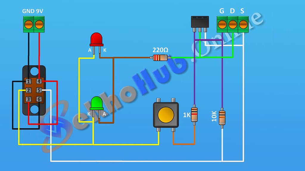
The IGBT and MOSFET tester uses a simple LED indicator system to show the conduction status of the transistor:
LEDs: Indicate whether the transistor is functioning correctly. Red and green LEDs can indicate ON/OFF or polarity.
220 Ω Resistor: Limits current through LEDs to prevent damage.
1k Resistor: Controls the gate or base of the device under test (DUT).
10k Resistor: Pull-down resistor prevents false triggering of the transistor.
DPDT Switch: Reverses polarity to test both N-channel/P-channel MOSFETs or IGBT types.
3-Pin Header: Connects the transistor under test.
2-Pin Terminal Block: Supplies 9V battery power to the circuit.
Working Principle:
When the DUT is inserted, pressing the DPDT switch applies voltage to the gate/base and drain/collector. If the transistor conducts correctly, the corresponding LED lights up. Flipping the DPDT switch tests the opposite polarity device.
This simple design avoids the need for microcontrollers while giving instant results.
Step-by-Step Assembly Guide
Prepare Your Board:
Mount all resistors, LEDs, and headers on a perfboard. Keep spacing for easy wiring.Wire the LEDs:
Connect each LED in series with a 220 Ω resistor. Place one LED for positive indication, one for negative.Install the Resistors:
Connect 1k resistor to the transistor gate/base.
Connect 10k resistor as a pull-down to ground.
Connect the DPDT Switch:
Wire the DPDT switch to allow polarity reversal, enabling testing of N/P-channel MOSFETs and IGBTs.Attach Terminal Blocks:
Connect 2-pin terminal block for the 9V battery input and 3-pin header for DUT.Connect Jumper Wires:
Complete all necessary connections, ensuring no short circuits.Power Up & Test:
Insert a known good MOSFET or IGBT. Flip the DPDT switch to check polarity. The LEDs will indicate if the device conducts properly.
Tips for Accurate Testing
Ensure the 9V battery is fully charged for consistent LED readings.
Double-check resistor placement to avoid burning LEDs.
Test known working transistors first to verify circuit operation.
Keep the tester portable for lab and field use.
FAQs
Q1: Can I test both N-channel and P-channel MOSFETs?
A1: Yes, the DPDT switch allows polarity reversal for both types.
Q2: How can I test IGBTs with this circuit?
A2: Insert the IGBT in the 3-pin header, apply voltage via DPDT switch, and observe the LEDs for conduction.
Q3: Do I need an Arduino for this tester?
A3: No, it is a non-Arduino, LED-based tester for quick checks.
Q4: What if LEDs don’t light up?
A4: Check battery voltage, connections, and confirm the device under test is functional.
Q5: Is this suitable for high-power devices?
A5: This is for low-power testing. High-power MOSFETs or IGBTs may require specialized testers.