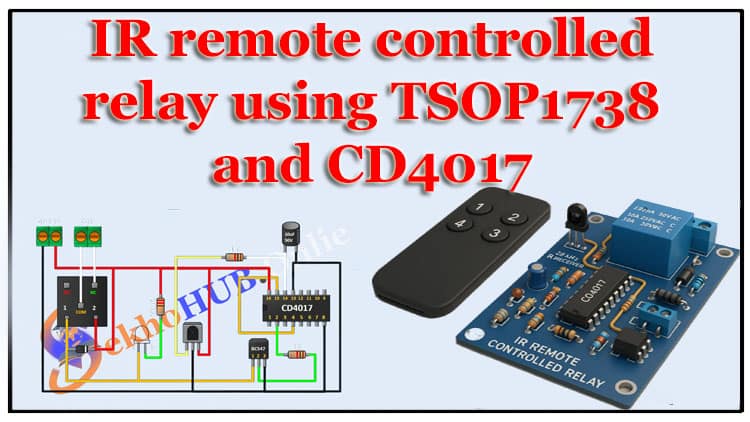
IR remote controlled relay circuit learn to build an IR remote controlled relay circuit that uses a TSOP1738 IR receiver, a CD4017 decade counter, and a BC547 transistor to drive a 6V relay. This IR remote controlled relay circuit tutorial covers the circuit diagram, BOM with buy links, step-by-step assembly, and testing.
Detailed troubleshooting for the IR remote controlled relay circuit is included so you can diagnose sensing, timing, and relay drive issues. Follow the step-by-step build guide to solder, wire, and test your IR remote controlled relay circuit. Safety and PCB layout tips for a robust IR remote controlled relay circuit are provided at the end.
Introduction
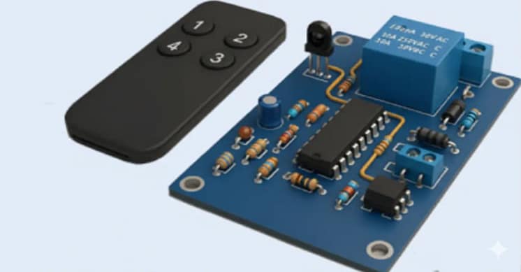
In this project, we’ll build an IR remote controlled relay circuit that lets you control any electrical or electronic device using a standard infrared (IR) remote—just like your TV remote. This circuit is based on the TSOP1738 IR sensor, CD4017 decade counter IC, and BC547 transistor to drive a 6V relay.
When you press a button on the remote, the TSOP1738 detects the IR signal and sends a pulse to the CD4017. The IC advances its output to toggle the relay, turning your connected load (like a light or fan) ON or OFF. The circuit is simple, inexpensive, and can be powered from a 5V–6V DC source.
This is a great DIY project for beginners and hobbyists to understand IR communication, transistor switching, and relay control in one compact design.
Materials for the Project
| Qty | Component | Value / type | Buy Link |
|---|---|---|---|
| 1 | TSOP1738 | 38 kHz IR receiver | Buy Link |
| 1 | CD4017 | CMOS decade counter (DIP-16) | Buy Link |
| 1 | 16-pin IC socket | DIP-16 IC base | Buy Link |
| 1 | BC547 | NPN transistor TO-92 | Buy Link |
| 1 | 6V relay | General-purpose SPDT, coil 6V | Buy Link |
| 1 | 1N4007 | Diode for flyback/protection | Buy Link |
| 1 | 10µF electrolytic cap | 10µF, 50V | Buy Link |
| 1 | 2-pin terminal block | Screw terminal 2-pin | Buy Link |
| 1 | Green LED | 5mm | Buy Link |
| 1 | Resistor | 1 kΩ | Buy Link |
| 1 | Resistor | 220 Ω | Buy Link |
| 1 | Misc | Perfboard or PCB, wires, soldering iron, multimeter | — |
Circuit diagram explanation
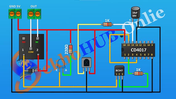
The schematic (based on your image) has these sub-blocks:
IR receiver stage (TSOP1738)
Power: Vcc = +5V, GND to the system ground.
Output: Active low pulses when a 38 kHz carrier is detected. The TSOP1738 outputs a demodulated digital stream corresponding to pressed remote buttons.
Clock/Sequencing (CD4017 decade counter)
The CD4017 advances its decoded output on every rising clock edge applied to its clock input (pin 14). In this design, the TSOP1738 output (after conditioning) is used to form a clean clock pulse so the CD4017 steps once per valid press.
Q0..Q9 outputs provide decoded lines; you can use one output for a single action, or multiple outputs for sequences.
Pulse conditioning & transistor driver (BC547)
The TSOP1738’s output may be inverted/active-low and noisy; a small RC or transistor buffer converts the demodulated pulse into a clean logic pulse. Use a 1 kΩ pull-up if necessary and a coupling capacitor if you need to convert a sustained low to a short pulse.
BC547 acts as a low-side driver for the relay coil: CD4017 output drives BC547 base via 1 kΩ, transistor sinks current through the relay coil to ground.
Relay & protection
Coil powered from 6V supply. Add a diode 1N4007 across coil (cathode to +6V, anode to transistor collector) as flyback protection. Add the capacitor (10µF) for noise suppression across supply if coils cause dips.
Powering
If using both +5V logic and +6V relay coil, common ground is essential. Vcc for CD4017 and TSOP1738 should be 5V; relay coil uses 6V if specified. Alternatively use a 5V relay for single-supply simplicity.
Download Circuit Diagram

How it works .
When you press a button on the remote, the IR LED in the remote sends a 38 kHz carrier modulated by data pulses.
TSOP1738 demodulates and outputs the data pulses (active low).
The pulses are shaped into single rising edges (one per button press) with an RC and optional transistor/buffer.
Each valid pulse clocks the CD4017 to increase its count; a particular CD4017 output (say Q0) goes HIGH.
The HIGH output drives the BC547 base (through 1k), switching the transistor and energizing the relay coil.
The relay contacts then switch the load (mains or low-voltage) connected to the terminal block. The LED and resistor show relay activation.
Step-By-Step Build Guide
Step 1.First mount the 16-pin IC socket on the perfboard or PCB, aligning the notch to indicate pin 1.
Step 2. Now insert the CD4017 into the socket with the notch toward the indicated end (pin 1 location).
Step 3. First solder the TSOP1738 on the board; connect its Vcc pin to +5V and GND to ground. Place the output pin where it can be routed to the clock conditioning network.
Step 4.Now connect a 10µF electrolytic capacitor across the +5V and ground near the TSOP to stabilize supply ripple.
Step 5.First place a 1 kΩ resistor from the CD4017 clock pin (pin 14) to the pulse-conditioning node (or from the TSOP output if no extra conditioning needed).
Step 6.Then wire the CD4017 reset (pin 15) to ground (unless you want an automatic reset on power-up—optionally add an RC power reset).
Step 7.Now route the chosen CD4017 output (for example Q0, pin 3) via a 1 kΩ resistor to the BC547 base.
Step 8.
First solder the BC547 with its emitter to ground, collector to the relay coil negative terminal, and base via the 1 kΩ resistor.
Step 9.Then connect the relay coil positive to the 6V supply, and place the 1N4007 diode across the coil (cathode to +6V, anode to transistor collector).
Step 10.Now add the LED and 220Ω resistor: LED anode to the selected CD4017 output (through 220Ω), LED cathode to ground, as an activation indicator.
Step 11.Then wire the 2-pin terminal block for the switched load use relay contacts (COM and NO) to the terminal block; ensure mains wiring safety if switching AC.
Step 12.Finally check all power rails, confirm common ground between 5V and 6V supplies, and connect power. Upload or perform final software tests in this hardware-only design, test by pressing the IR remote and observing relay action.
Circuit diagram notes and common pitfalls
Grounding: All grounds (5V logic and 6V relay return) must be common. Missing common ground is the most common fault.
TSOP orientation: The TSOP1738 has a defined front (IR sensing window) don’t place it facing away from the remote.
Debounce / repeat: Most remotes send repeated bursts while holding a button; add simple debouncing (one-shot) so the CD4017 steps once per distinct press if desired. A small capacitor + resistor or a monostable can achieve this.
Relay coil voltage: Use relay coil voltage matching your supply; do not run a 6V coil from 5V unless tolerant. Alternatively use a 5V relay and a single 5V supply.
Isolation: For AC loads, place the relay and AC wiring away from logic traces; maintain creepage/clearance and use insulating barriers.
Testing & debugging checklist
With power off, verify continuity and correct pin wiring.
Power up and measure +5V at the CD4017 Vdd and TSOP Vcc pins.
Point a remote and press a button; measure the TSOP output with a scope or logic probe — you should see pulses (active low).
Confirm the CD4017 advances outputs when pulses are applied.
Check transistor base voltage when CD4017 output is HIGH — it should be ~0.7V above emitter through 1k.
If relay doesn’t energize, check coil voltage, transistor orientation, and diode polarity.
FAQs
Q: Can I power the whole circuit from a single 5V supply?
A: Yes — if you use a 5V relay or a relay driver rated for 5V. If the relay coil requires 6V, you need a separate 6V supply or a boost converter; keep grounds common.
Q: Will any IR remote work?
A: The TSOP1738 responds to 38 kHz-modulated IR carriers used by many consumer remotes. Most remotes use either NEC, RC5, or Sony protocols — TSOP1738 will demodulate the carrier regardless of protocol, but you may see repeated pulses while holding a button.
Q: How to make it toggle on one press and off on next press?
A: Use the CD4017 outputs as a one-step latch or use a flip-flop (e.g., a T flip-flop) or use the CD4017 to set/reset on alternating outputs.
Q: Can this be used for mains?
A: Yes with caution. Use a relay rated for mains current and follow safety standards (isolation, enclosures). If switching high current, consider using an opto-isolated relay board or a triac/solid-state relay with proper snubbers.
Conclusion
The IR remote controlled relay circuit is a practical and easy-to-build project that demonstrates the use of infrared communication to control electrical loads. By combining the TSOP1738 IR receiver, CD4017 decade counter IC, and BC547 transistor, we can create a simple system that responds to standard IR remotes to switch a 6V relay ON and OFF.
This project not only helps in learning about IR sensors and relay interfacing but also provides a useful application for home automation. You can extend the design to control multiple devices by using additional CD4017 outputs or integrating it with a microcontroller.
With careful soldering and testing, this circuit becomes a reliable remote-controlled switch system — ideal for lamps, fans, or other low-power appliances. It’s a great foundation for more advanced automation projects.


