

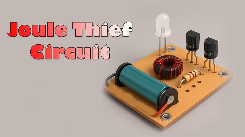
Joule Thief Circuit Using a BC547 Transistor and Common Resistors.
Introduction.
A joule thief circuit enables the battery to light an LED in the circuit even if that LED requires more battery power. For example, a 1.85V LED can be lit by a 1.5V battery cell through this circuit. Hence, it allows the dead battery cells to drive the LED loads. In short, the joule thief circuit is the voltage booster circuit that transforms the input voltage into a greater periodic voltage value. However, the circuit does not boost current. Since it steals energy, or joules, that’s why they named their circuit joules. This small circuit is also referred to as a joule ringer, blocking oscillator, and vampire torch.
The joule thief circuit can be made using different methods. We are going to build this circuit with two transistor methods. Thus, the circuit requires very cheap components, including transistors, coils, capacitors, and LEDs as its main elements. Also, it’s easy to handle and simple to create.
Materials for the Project
- 2X BC547 Transistors
- 1X 220 pF Ceramic Capacitors
- 2X 22K, 330-ohm resistors
- 1X LED
- 1X 100uH Coil
- 1X Battery cell (1.5V)
BC547 Pinout.
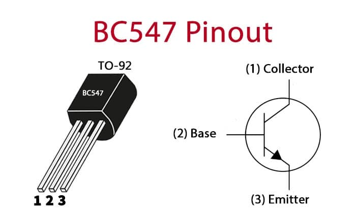
✅ Pin Details
Pin 1 – Collector (C): Connects to the load or positive side of the circuit.
Pin 2 – Base (B): Controls the transistor; a small current here turns the transistor ON.
Pin 3 – Emitter (E): Connects to ground or the negative side of the circuit.
How the Joule Thief Works
A Joule Thief is a self-oscillating boost converter. It uses an inductor and transistor to rapidly switch current on and off. This switching action causes a voltage spike that is high enough to power devices like LEDs—even from voltages below their normal forward voltage.
For example: A white LED usually needs 3.0V. The Joule Thief lets it run from a 1.0V or even 0.9V cell.
Download Circuit Diagram

Application and Uses
- Firstly, the circuit can be utilized to build an LED flashlight.
- Moreover, with some changes, it can be used as a blocking oscillator that generates narrow pulses.
- To drive small loads through a dying battery. Additionally, this circuit can be adapted for use in various electronic projects, such as creating sound effects or controlling motors. Its versatility makes it an excellent choice for hobbyists and engineers alike.
Working Explanation
The circuit operates by the 1.5V battery cells. A magnetic field developed around the coil because the current passes through the wire’s coil.
As a result, it induces a greater amount of electricity in the coil, which is given to the base of transistor Q2 and opens the collector-emitter channel. The built-up energy of the circuit can’t go through the transistor, so it goes through the load, which is the LED.