
 Laser Distance Meter Using Arduino Nano | Step-by-Step DIY Electronics Project
 Laser Distance Meter Using Arduino Nano | Step-by-Step DIY Electronics Project
Learn how to build a Laser Distance Meter using Arduino Nano with an OLED display and VL53L0X sensor. This Laser Distance Meter DIY project is beginner-friendly and provides accurate distance measurements. Follow this guide to assemble your Laser Distance Meter step-by-step, connect the Arduino Nano, OLED, and VL53L0X sensor. Understand the working principle behind the Laser Distance Meter, including wiring, code, and calibration.
Perfect for DIY electronics enthusiasts, this Laser Distance Meter project includes a complete BOM list, circuit diagram, and programming instructions. Enhance your electronics skills with this practical Laser Distance Meter, learn how to troubleshoot common issues, and create your own measuring tool. Start your Laser Distance Meter project today and enjoy precise, real-time distance readings with this detailed Arduino tutorial.
Introduction
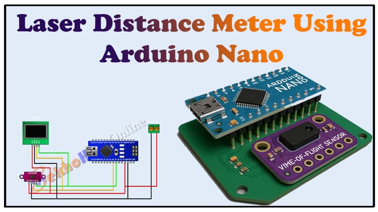
Measuring distance accurately is now easy with the Laser Distance Meter project using Arduino Nano. This DIY electronics project leverages the VL53L0X Time-of-Flight (ToF) laser sensor and OLED display for real-time distance measurement. It’s compact, easy to assemble, and perfect for hobbyists, students, and engineers looking to experiment with precision sensing.
With just a few components Arduino Nano, OLED display, VL53L0X sensor, and jumper wires you can create a portable Laser Distance Meter that’s accurate and reliable.
Materials for the Project
| S.No | Component | Quantity | Buy Link |
|---|---|---|---|
| 1 | Arduino Nano | 1 | Buy Link |
| 2 | OLED Display 0.96” I2C | 1 | Buy Link |
| 3 | VL53L0X Time-of-Flight Sensor | 1 | Buy Link |
| 4 | 2 Pin Terminal Block | 1 | Buy Link |
| 5 | Jumper Wires | 1 Set | Buy Link |
| 6 | Perfboard (optional) | 1 | Buy Link |
Useful Tools
| Tool | Quantity | Purpose / Notes | Click & Buy |
|---|---|---|---|
| Soldering Iron Kit | 1 | For making permanent connections | Click & Buy |
| Solder Wire (60/40, 0.8mm) | 1 | Electrical soldering | Click & Buy |
| Wire Stripper & Cutter | 1 | Stripping jumper wires | Click & Buy |
| Mini Screwdriver Set | 1 | For module and relay terminal screws | Click & Buy |
| Multimeter | 1 | Testing voltages and continuity | Click & Buy |
| Hot Glue Gun (optional) | 1 | Securing components in place | Click & Buy |
| Small Pliers | 1 | Holding and bending wires | Click & Buy |
| Heat Shrink Tubing Set | 1 | Insulating exposed wires | Click & Buy |
Download Circuit Diagram

Circuit Diagram
Here’s how to connect the components
VL53L0X Sensor
VCC → 5V on Arduino Nano
GND → GND on Arduino Nano
SDA → A4 on Arduino Nano
SCL → A5 on Arduino Nano
OLED Display (I2C)
VCC → 5V on Arduino Nano
GND → GND on Arduino Nano
SDA → A4 on Arduino Nano (shared with VL53L0X)
SCL → A5 on Arduino Nano (shared with VL53L0X)
2 Pin Terminal Block
Use to connect external power if needed
Note: Both OLED and VL53L0X use I2C, so SDA and SCL are shared.
Step-by-Step Build Guide
Prepare the Arduino Nano
Connect Arduino Nano to your computer via USB.
Install the Arduino IDE and required libraries:
Adafruit_SSD1306for OLED displayAdafruit_VL53L0Xfor VL53L0X sensor
Connect the VL53L0X Sensor
Connect VCC, GND, SDA, SCL as per the circuit diagram.
Connect the OLED Display
Connect VCC, GND, SDA, and SCL. Make sure SDA/SCL pins are shared with the sensor.
Power and Ground Setup
Use the 2 Pin Terminal Block for external 5V power if required.
Ensure proper grounding for stability.
Upload the Arduino Code
Install libraries via Arduino IDE Library Manager.
Use the sample code below:
Testing the Laser Distance Meter.
Power your Arduino Nano.
Watch the OLED display update distance measurements in real-time.
Ensure sensor faces the target surface for accurate reading.
Working Principle
VL53L0X Sensor uses Time-of-Flight laser technology to measure distance.
The sensor emits a laser pulse, measures the reflection time, and calculates the distance.
Arduino reads the sensor data via I2C and displays it on the OLED display.
Tips for Accuracy
Ensure the sensor is stable and properly aligned with the target.
Avoid reflective or transparent surfaces; they can affect readings.
Use a small perfboard to mount components for a clean build.
FAQs
Q1: What is the max distance of the VL53L0X sensor?
Around 2 meters in standard lighting conditions.
Q2: Can I power this project with a battery?
Yes, a 5V USB power bank works well.
Q3: Can I use a bigger OLED display?
Yes, ensure the library supports the new resolution.
Q4: Is this project beginner-friendly?
Absolutely, it’s perfect for learning I2C, Arduino coding, and sensors.
Q5: Can I use multiple VL53L0X sensors at once?
Yes, but you need to handle I2C addresses for multiple sensors.