
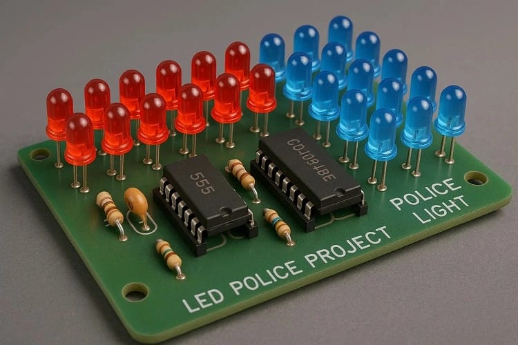
Building an LED Police Light Project is a great way to explore practical timing control, sequential flashing, and LED driving methods used in visual signaling systems. This design recreates the familiar red and blue chase effect by combining a 555 timer with a shift-register-based sequence driver. Through this project, you learn how pulses flow through logic stages and how LEDs respond to controlled switching cycles.
Hobbyists enjoy creating these compact emergency-style lights because the core idea is simple, yet the behavior looks technically impressive. With components arranged carefully, you can reproduce patterns similar to police strobe light circuit, LED flasher using 555, CD4094 shift register output, red and blue LED pattern, and emergency light sequence systems.
How the Circuit Works
Pulse Generation With the Timer Stage
At the core sits the 555 IC, which serves as an astable oscillator producing a continuous pulse. This stage handles pulse generation, where the frequency can be adjusted using a trimpot and capacitor combination. The pulse establishes the base Timing at which the LEDs flicker and propagate through the sequence.
This matches the behavior expected in a professional police strobe light circuit, and the technique is commonly used in many LED flasher using 555 builds.

Shift Register Logic and Sequence Propagation
The output of the timing stage enters a CD4094 shift register output section. This IC takes the single-line pulses and shifts them across multiple output pins in sequential order. This method supports:
Sequence formation
Pattern switching
Propagation of a ripple-like flow
Step-by-step LED illumination

This explains how police-style lighting patterns work, especially when multiple LEDs run in alternating directions. The shift register operation forms a tidy chain of events where each LED lights in a controlled rhythm.
LED Driving and Current Regulation
Each LED is paired with a Resistor to maintain safe Voltage and current levels. This part ensures proper LED current limiting, prevents overheating, and avoids premature LED wear.
In some designs, a transistor LED driver stage is used, but our build remains straightforward, staying aligned with beginner labs and hobby electronics project standards.
Flash Speed Control With Trimpot
Using the trimpot allows adjusting flash rate using a trimpot, which directly affects the oscillator inside the timer stage. Slowing or accelerating the pulses changes how the LEDs chase one another. It also plays role in flashing interval adjustment, giving full manual control over the effect.
LED Arrangement and Color Flow
The LEDs are divided into:
8 × Red
8 × Blue
The red and blue LED pattern creates the familiar alternating effect. Paired with sequential logic, this produces authentic LED chaser effects similar to emergency light sequence products.

Power Considerations
You need regulated Voltage nearby, typically 9–12V. Capacitors provide DC supply filtering, ensuring a clean supply and smooth LED behavior. For bikes and cars, following safe automotive LED installation guidelines is crucial.
For beginners, assembling this circuit on a prototype board resembles building a breadboard police light model.
Components Required
| Component | Quantity | Description | Buy Link |
|---|---|---|---|
| 555 Timer IC | 1 | Pulse generator | Buy Link |
| CD4094 IC | 1 | Shift register | Buy Link |
| LEDs (Red) | 8 | 5mm high-brightness | Buy Link |
| LEDs (Blue) | 8 | 5mm high-brightness | Buy Link |
| 1kΩ Resistor | 18 | Limit current for LEDs | Buy Link |
| 10kΩ Resistor | 1 | Timer section | Buy Link |
| 10kΩ Trimpot | 1 | Flash speed control | Buy Link |
| 100nF Capacitor | 1 | Noise filter | Buy Link |
| 10µF Capacitor | 1 | Timing stabilization | Buy Link |
| 100µF Capacitor | 1 | Power smoothing | Buy Link |
| Perfboard | 1 | PCB base | Buy Link |
| Jumper Wires | – | General wiring | Buy Link |
LED Police Light Project Circuit Diagram

The diagram shows:
Timer section forming continuous pulses
Module (CD4094) receiving timing signals
LEDs connected via resistors, mapped to outputs
Capacitors smoothing the supply
Adjustable trimpot wired into the Timing network
The signal starts as an oscillation → becomes a shift sequence → generates a recognizable emergency blink effect.
Step-by-Step Build Guide
Step 1.
Gather the ICs, LEDs, resistors, capacitors, perfboard, switches, and jumper wires.
Step 2.
Place the 555 Timer on the board and identify pins for VCC, GND, Trigger, Threshold, Discharge, and Output.
Step 3.
Wire the Timer into astable mode by adding a 10k resistor, trimpot, and timing capacitors.
Step 4.
Connect the pulse generation output to the CD4094 clock input.
Step 5.
Place the shift register and make connections for latch, data, and clock pins.
Step 6.
Attach the red and blue LEDs in the desired order along the board.
Step 7.
Add one Resistor per LED to maintain proper current.
Step 8.
Connect the final outputs from the CD4094 to each LED-resistor pair.
Step 9.
Install the 100µF capacitor across supply rails for DC supply filtering.
Step 10.
Adjust the Speed of flashing by rotating the trimpot.
Final Step.
Apply a 9–12V supply and check the Sequence movement and Pattern accuracy before mounting on a bike or car.
LED Police Light Project Working Principle
The design uses a pulse from the Timer to move data through a shift register. The LED states propagate along the line, forming a moving bar of flashing colors. This is the core concept behind the LED Police Light Project working principle, explaining the relationship between a logic IC and sequential lighting behavior.
Applications
Bike handlebar lighting
Dashboard emergency indicator
Decorative display
Educational demonstration in labs
Sequential lighting for models or DIY kits
Small car/bike accessory lighting systems
Check related DIY builds on SekhoHub.online in the DIY Projects and Electronics Projects categories.
Troubleshooting
LEDs Not Flashing
Check the Timer section and make sure the Output pin is generating pulses.
Incorrect Sequence
Check wiring between CD4094 and LED pins.
Brightness Fluctuation
Verify LED current limiting resistors.
Timer Not Oscillating
Replace the 10µF capacitor or trimpot.
Only One Color Works
Confirm wiring along the Pattern chain.
Safety Precautions
Don’t mount emergency-looking lights on public roads illegally.
Ensure electrical insulation in vehicles.
Keep wiring secured.
Maintain proper Voltage rating.
Avoid overheating.
FAQs
How does a police light work?
Police lights work by rapidly flashing LEDs in alternating colors using timing circuits and controllers to create attention-grabbing patterns.
How to create a LED light circuit?
You create an LED circuit by adding LEDs with resistors to a power source and controlling them with a timer IC or microcontroller.
How does the LED emergency light work?
LED emergency lights use timed pulses to flash LEDs in repeating sequences that mimic warning or alert signals.
Are police lights legal or illegal?
Police-style lights are illegal on public roads for civilian vehicles but allowed for authorized emergency services.
Is there any challan for LED lights?
Yes, using unauthorized flashing LED lights on vehicles can result in a challan depending on local traffic laws.
Can you use police lights on private property?
Yes, police-style lights may be used on private property for display or educational purposes as long as you don’t drive with them on public roads.
This is also relatable to SekhoHub.online.
Conclusion
This LED Police Light Project demonstrates how timing pulses, shift registers, LED drivers, and color sequences collaborate to form a recognizable flashing pattern. By combining a simple Timer, a Module for logic control, and well-tuned LEDs, you create a compact, reliable, and visually engaging accessory suitable for demonstrations, learning environments, or DIY models.
If you want more projects like this, visit SekhoHub.online for full circuit guides, PCB ideas, and detailed wiring tutorials.