
Introduction
The MAX7219 Dot Matrix Display offers a practical way to control large groups of LEDs through a single driver IC, making it ideal for compact visual interfaces and Arduino-based projects. Instead of wiring each LED individually, the module uses an internal scanning system that simplifies control and keeps the display stable.
With only a few data lines required, engineers can build scrolling text panels, indicators, and compact dashboard displays with ease. The module integrates features such as brightness control, multiplexing, SPI communication, daisy chaining, and row-column scanning, allowing smooth operation even in multi-display setups. Its reliability makes it a preferred choice for many DIY and professional builds.

Module Overview
The MAX7219 module is a compact LED driver board designed to control 64 individual LEDs in an 8×8 matrix or eight 7-segment displays. It handles all the complex scanning and current regulation internally, freeing your microcontroller from repetitive refresh tasks. Combined with a simple SPI-based communication interface, the module becomes ideal for building multi-display arrays for scrolling text, animations, and data dashboards.
Types of MAX7219 Modules
Generic Module
The standard module includes:
MAX7219 IC
Single 8×8 LED matrix display
PCB with five input pins and five output pins
Current-setting resistor (RSET)
Power filtering capacitors
FC-16 Standard Module
This version is optimized for chaining multiple displays—commonly used for long running text boards. Its PCB layout is standardized, making it easier to align modules in straight rows.
8×8 Dot Matrix Display Structure
An 8×8 LED matrix is organized as:
8 rows (R0–R7)
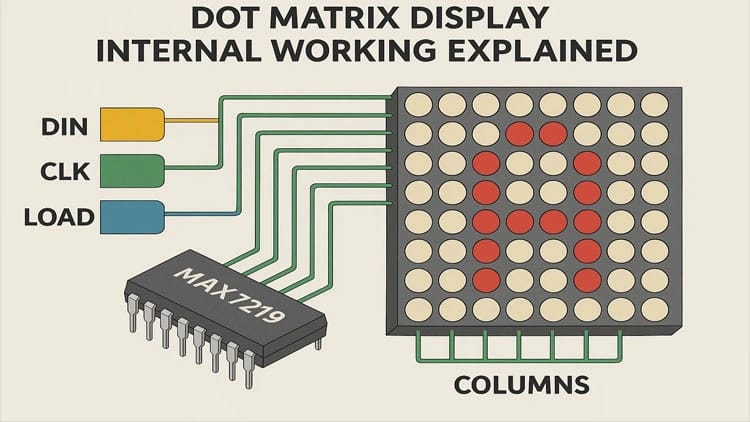
8 columns (C0–C7)
Each LED sits at a row-column intersection. Instead of driving 64 LEDs individually, the matrix uses multiplexing, drastically reducing required connections.
Understanding Multiplexing
Multiplexing enables control of many LEDs with fewer pins.
How It Works
Only one row is active at a time.
The MAX7219 selects the row and then activates the column lines corresponding to the LEDs that should light in that row.
The process repeats for all eight rows at high speed.
Because switching happens faster than human perception, the display appears fully lit and stable.
How the MAX7219 Chip Manages Multiplexing
The internal circuitry includes:
8-digit scan registers
8×8 display RAM
Brightness control logic
Decode mode control
Current regulation network
Shutdown mode logic
SPI serial interface
The chip cycles through RAM automatically, refreshing rows at up to 800 Hz. This eliminates load on the microcontroller—one of the main advantages of using MAX7219 for LED driving.
Hardware Brightness Control
The RSET resistor sets the maximum LED segment current.
Typical RSET values:
28 kΩ for standard red LED matrices
20–24 kΩ for brighter variants
Software Brightness Control
Brightness is adjustable from 0 to 15 using intensity register commands sent via SPI.
MAX7219 Pinout Explanation
Input Pins
VCC – 5V supply
GND – Ground
DIN – Serial data input
CS / LOAD – Chip select
CLK – Serial clock
Output Pins (for daisy chaining)
DOUT – Forward data to next module
LOAD – Chip select to next module
Wiring the MAX7219 Module to Arduino
A typical single-module connection uses:
| MAX7219 Pin | Arduino Pin |
|---|---|
| VCC | 5V |
| GND | GND |
| DIN | D11 (MOSI) |
| CLK | D3 (SCK) |
| CS | D10 |
Daisy Chaining Multiple Modules
To extend displays for long text:
Connect DOUT of module 1 → DIN of module 2
Share VCC, GND, CLK, and CS
Continue chaining as required
This allows dozens of displays to run from the same three control lines.
Circuit Diagram Explanation

Below is a simplified explanation of the schematic:
MAX7219 sits at the center handling row and column drivers.
Capacitors filter noise:
10 µF across VCC/GND
104 nF close to the IC
RSET resistor limits current and defines LED brightness.
SPI lines from Arduino communicate through DIN, CLK, and CS.
Matrix rows/columns directly connect to MAX7219 internal transistor drivers.
Bill of Materials
Step-by-Step Build Guide
Step 1. Prepare your components
Gather the MAX7219 module, Arduino board, and jumper wires.
Step 2. Connect power lines
Connect VCC to 5V and GND to Arduino ground.
Step 3. Connect the SPI lines
Attach DIN to Arduino MOSI (D11), CLK to D13, and CS to D3.
Step 4. Verify connections
Ensure wires are tight and polarity is correct.
Step 5. Install required libraries
Install LedControl.h or MD_MAX72XX from Arduino Library Manager.
Step 6. Upload basic test code
Run a simple LED-on test to verify communication.
Step 7. Test brightness levels
Use intensity commands to confirm PWM brightness control.
Step 8. Add multiple modules (optional)
Daisy chain additional matrices by linking DOUT → DIN.
Step 9. Upload scrolling text code
Display messages, numbers, or animations.
Step 10. Final testing and optimization
Check refresh stability, brightness uniformity, and smooth scrolling.
Arduino Example Code
Applications of MAX7219 Dot Matrix Displays
Scrolling text banners
Digital clocks
Temperature displays
Arduino scoreboards
IoT message notifications
Industrial counters and timers
Educational projects
DIY information boards
Animated icons and patterns
Sensor dashboard displays
For more project ideas, check the display section at SekhoHub.online.
Troubleshooting
| Problem | Cause | Solution |
|---|---|---|
| Display not lighting | Incorrect wiring | Recheck VCC, GND, DIN, CLK, CS |
| Flickering | Weak power supply | Use external 5V source |
| One row dead | Faulty matrix | Replace display |
| Chaining failure | Incorrect DOUT→DIN | Reconnect chain wiring |
FAQs
How does dot matrix display work?
A dot matrix display lights LEDs arranged in rows and columns using multiplexing, activating one row at a time so the combined pattern forms characters or graphics.
How does the MAX7219 work?
The MAX7219 drives an 8×8 LED matrix by handling multiplexing, current control, and refreshing internally while receiving commands through SPI.
How does matrix display work?
A matrix display controls LEDs or pixels by selecting rows and columns rapidly, creating visible text or patterns through high-speed scanning.
How does matrix LED work?
Matrix LEDs use a grid layout where individual LEDs turn on based on row-column activation controlled through multiplexing.
What is the difference between LCD and dot matrix display?
An LCD uses liquid crystals and a backlight to form images, while a dot matrix display uses LEDs arranged in a grid to emit light directly.
Conclusion
The MAX7219 module dramatically simplifies LED matrix control by managing multiplexing, brightness, and refresh timing internally. Its SPI interface minimizes wiring complexity, while daisy chaining provides near-limitless display expansion. With straightforward Arduino libraries, this module becomes a perfect tool for creating interactive signage, counters, and real-time dashboards. Whether you’re a hobbyist exploring your first LED matrix or an engineer crafting a multi-panel display, the MAX7219 ensures clean visuals, minimal microcontroller load, and professional-grade results.