

The Mic Connection with PAM8403 is an essential step when building compact audio amplification projects that require clear and stable sound input. Since microphones generate very low-level signals, proper interfacing is necessary before feeding audio into the PAM8403 amplifier module. Using a suitable electret microphone amplifier, the mic signal can be boosted to a level the PAM8403 can handle without distortion. This setup is widely used in portable speakers, intercoms, and DIY audio systems. Correct grounding, shielding, and biasing play a major role in reducing noise and hum. With careful wiring and basic components, audio preamplifier circuit integration ensures reliable sound reproduction and protects the amplifier input stage.
Materials for the Project
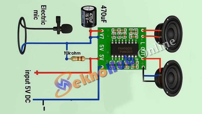
PAM8403 Stereo Audio Amplifier Module (5V DC)
Electrolytic Capacitor – 470 µF (16V)
Resistor – 10k ohm
5V DC Power Source (USB, Battery, or Adapter)
Two Mini Speakers (Left & Right output)
Circuit Description:
Microphone Section:
The electric mic captures sound waves and converts them into analog electrical signals.
The 470 µF capacitor is connected in series to filter DC and pass only the audio signal.
A 10k ohm resistor is used to bias the mic from the 5V power line.
Amplifier Module (PAM8403):
The filtered signal from the mic is fed to the input pin (L-IN) of the PAM8403.
The module amplifies this audio signal and sends it to the connected left and right speakers.
Power Supply:
The amplifier operates at 5V DC, which makes it ideal for USB or portable battery-powered projects.
Download Circuit Diagram
Features:
Low power consumption (only 5V required)
Stereo output for better sound experience
Compact and suitable for portable or DIY audio projects
Perfect for intercoms, voice-controlled systems, Arduino sound input, and more
Applications:
DIY Bluetooth Speakers
Audio Intercom System
Voice Playback or Recording
Mini Audio Amplifier Projects
Basic Sound Detection Systems
FAQs
How to connect the mic?
Connect the mic signal pin to the audio input, ground to GND, and supply bias voltage if the microphone requires it.
What connection does a mic use?
Most microphones use 3.5 mm jack, XLR, or simple two/three-wire connections depending on electret or dynamic type.
How to connect mic with mobile?
Use a 3.5 mm TRRS headset jack or an OTG audio interface that supports external microphones.
How to connect mic to PC?
Plug the mic into the PC’s mic input jack, USB sound card, or USB microphone interface.
How to connect a wired mic?
Identify signal, ground, and bias wires, then connect them correctly to the audio input circuit or device.