

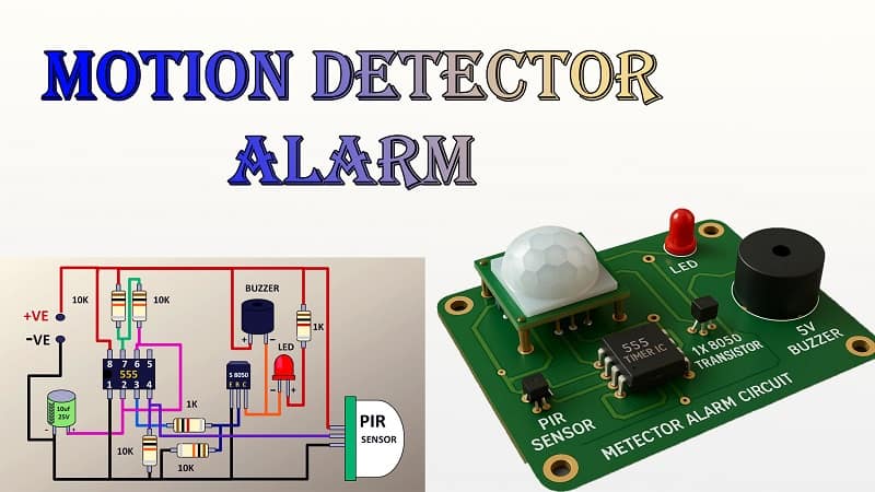
How to Build a Powerful Motion Detector Alarm Circuit Using PIR Sensor and 555 Timer in 8 Easy Steps
This detailed step-by-step guide explains how to build a motion detector alarm circuit using a PIR sensor, a 555 timer, and basic electronic components. The motion detector alarm circuit is ideal for home security, DIY projects, and learning electronics. In this tutorial, we use the motion detector alarm circuit with LED and buzzer output to alert when movement is detected.
Whether you are a beginner or an experienced hobbyist, this motion detector alarm circuit is easy to assemble on a Vero board. Our design uses only low-cost components. The motion detector alarm circuit is explained with a schematic, a bill of materials, and a practical assembly method. By following this guide, you can build your own motion detector alarm circuit in under an hour. This motion detector alarm circuit project will help you understand timing circuits, sensors, and transistor-driven outputs in electronics.
Introduction
Over my 10 years working with electronics, I’ve built countless motion-based security devices—but one of the simplest and most effective is the motion detector alarm circuit.
This design uses:
- A PIR (Passive Infrared) sensor to detect movement.
- A 555 timer IC in monostable mode to create a timed alert signal.
- An S8050 transistor to amplify the signal and drive both a buzzer and an LED indicator.
We’ll be assembling this on a Vero board, making it ideal for hobbyists who don’t have access to PCB manufacturing.
This project is great for:
- Home security
- Garage or workshop monitoring
- Simple school/college electronics demonstrations
Download Circuit Diagram
How the Motion Detector Alarm Circuit Works
At its core, the PIR sensor detects infrared radiation changes caused by moving objects (like a person walking). When triggered, it sends a short HIGH signal to the 555 timer.
The 555 is wired in monostable mode:
- When triggered, its output goes HIGH for a set duration determined by the resistor–capacitor (RC) timing network.
- In our design, the timing network uses a 10 kΩ resistor and a 10 µF capacitor, giving a delay of roughly 1 second per trigger.
This HIGH output drives the S8050 transistor, which switches the LED and buzzer ON, providing both visual and audible alerts.
Materials for the Project (Motion Detector Alarm Circuit)
| S.No | Component | Quantity | Specification | Purpose |
| 1 | PIR Sensor | 1 | HC-SR501 type | Motion detection |
| 2 | 555 Timer IC | 1 | NE555 | Monostable timer |
| 3 | 8-pin IC Base | 1 | Standard DIP | Socket for 555 |
| 4 | Resistor | 2 | 1 kΩ, 1/4 W | LED current limit, bias |
| 5 | Resistor | 4 | 10 kΩ, 1/4 W | Timing network, pull-down |
| 6 | Capacitor | 1 | 10 µF, 25V electrolytic | Timing capacitor |
| 7 | LED | 1 | 5 mm, red | Visual indication |
| 8 | Transistor | 1 | S8050 NPN | Drives buzzer & LED |
| 9 | Buzzer | 1 | 5V piezo type | Audible alert |
| 10 | Female Header | 1 | 3-pin | PIR sensor connection |
| 11 | Vero Board | 1 | Small section | Circuit assembly |
| 12 | Jumper Wires | As needed | Various lengths | Interconnections |
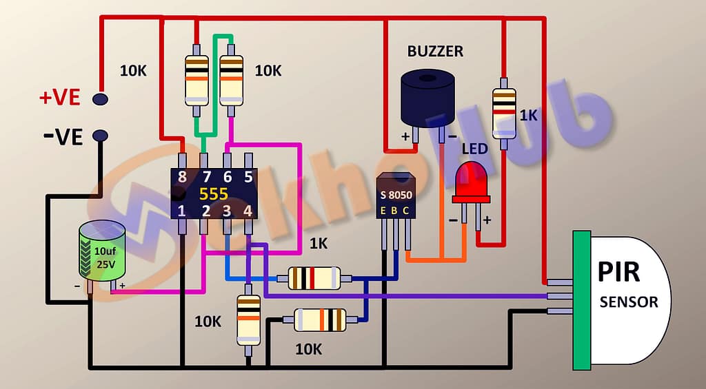
Circuit Diagram Explanation
- PIR Sensor Output
The PIR’s OUT pin connects to the 555 trigger pin (pin 2). Its VCC goes to +5V, and GND to ground. - 555 Timer Monostable Mode
- Pin 6 (threshold) and pin 2 (trigger) are connected together.
- The timing resistor and capacitor set the output ON duration.
- Pin 4 (reset) is tied to +5V to avoid unwanted resets.
- Pin 3 (output) drives the transistor base.
- Transistor Driver Stage
The S8050’s base is fed through a 1 kΩ resistor from the 555 output. When active, it pulls current through the buzzer and LED (in parallel, each with an appropriate series resistor). - Power Supply
The entire circuit operates from +5V regulated DC. This can be from a USB adapter, battery pack, or regulated supply.
Video Tutorial
Step-by-Step Build Guide
Step 1: Prepare the Vero Board
- Cut a small section of Vero board (around 20 × 15 holes).
- Mark component placement to minimize wiring length.
Step 2: Mount the 8-pin IC Base
- Insert the IC base in the center; leave room for resistors and capacitors around it.
Step 3: Install Resistors and Capacitor
- Fit the 1 kΩ resistors for the LED and transistor base.
- Fit the 10 kΩ resistors for the timing network and pull-downs.
- Insert the 10 µF capacitor with correct polarity.
Step 4: Add PIR Sensor Header
- Solder the 3-pin female header at one side of the board.
- Connect its pins to +5V, GND, and the trigger line.
Step 5: Wire the 555 Timer Circuit
- Follow the monostable wiring diagram: connect pins 2 & 6, tie pin 4 to VCC, and connect the RC network to pins 6/7.
Step 6: Add the Transistor Output Stage
- Place the S8050 transistor; wire its base to pin 3 of the 555 via a 1 kΩ resistor.
- Connect its collector to the buzzer and LED (with resistor).
- Emitter to ground.
Step 7: Install LED and Buzzer
- Position the LED on the front edge for visibility.
- Connect the buzzer in parallel for sound output.
Step 8: Power Up and Test
- Insert the 555 IC into the socket.
- Power the board with a +5V supply.
- Wave your hand in front of the PIR—the LED and buzzer should activate for the set duration.
Practical Tips
- To increase alert time, use a larger capacitor (e.g., 47 µF) or resistor.
- Keep the PIR sensor away from heat sources to avoid false triggers.
- Use shielded wires for long PIR connections to reduce noise.
Applications
- Home/office intrusion detection
- Garage motion alerts
- Pet movement monitoring
- Energy-saving automatic alerts
FAQs
Q1: Can I use a 9V battery?
Yes, but ensure you regulate it down to 5V for the PIR and 555 to prevent damage.
Q2: How far can the PIR detect motion?
Typically 5–7 meters, depending on sensitivity settings.
Q3: Can I drive a relay instead of a buzzer?
Yes, but use a transistor rated for the relay coil current.
Q4: Can I use S9014 instead of S8050?
Yes, if the load current is small (less than 100 mA).
Working Explanation of the Motion Detector Alarm Circuit
The motion detector alarm circuit works in three main stages:
1. Motion Detection (PIR Sensor Stage)
The PIR sensor detects infrared radiation changes caused by movement in its field of view (like a person walking past).
When motion is detected, the sensor’s OUT pin goes HIGH (around 3.3V–5V).
This HIGH signal is sent to pin 2 (trigger pin) of the 555 timer.
2. Timing Control (555 Timer Monostable Stage)
The 555 timer IC is wired in monostable mode.
When pin 2 receives the LOW-to-HIGH trigger pulse from the PIR sensor, the 555 output (pin 3) goes HIGH for a fixed duration.
The ON time is set by the resistor–capacitor (RC) network:
R = 10 kΩ
C = 10 µF
This gives about 1 second of ON time.
T = 1.1 × R × C
This prevents the buzzer from sounding for just a fraction of a second—instead, you get a steady alarm for the set time.
3. Output Driving (Transistor and Load Stage)
The HIGH output from pin 3 of the 555 is fed through a 1 kΩ resistor to the base of the S8050 NPN transistor.
The transistor acts as a current amplifier, powering both:
LED (visual alert) with a series resistor.
5V buzzer (audible alert).
Both are connected in parallel to the transistor’s collector, with the emitter connected to ground.
Sequence of Operation
No motion → PIR output is LOW → 555 output is LOW → buzzer and LED are OFF.
Motion detected → PIR sends HIGH signal → triggers 555 timer.
555 output goes HIGH for the set time → transistor turns ON → LED + buzzer activate.
After time elapses, 555 output returns LOW → transistor switches OFF → LED + buzzer turn OFF