
 How To Make MPPT Solar Charge Controller | MPPT 4.0
 How To Make MPPT Solar Charge Controller | MPPT 4.0
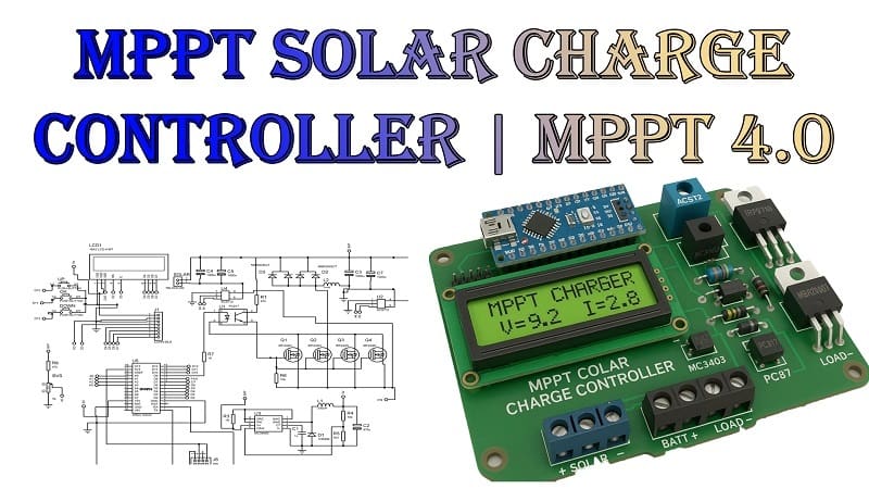
As solar energy becomes increasingly popular, maximizing efficiency has never been more important. One of the smartest ways to do this is by building your own MPPT (Maximum Power Point Tracking) solar charge controller. This project—MPPT 4.0—uses an Arduino Nano, real-time current sensing, and intelligent voltage tracking to ensure your solar panels are operating at their highest potential.
In this tutorial, you’ll learn how to design and build a DIY MPPT solar charge controller using components like the MC34063 IC, IRF3710 MOSFETs, ACS712 sensor, PC817 optocoupler, and MBR20100CT diodes, among others.
✅ What is an MPPT solar charge controller?
MPPT stands for Maximum Power Point Tracking. It is an advanced technique used in solar charge controllers to extract the maximum available power from a solar panel by continuously tracking and adjusting the operating point.
In contrast to conventional PWM (Pulse Width Modulation) charge controllers, MPPT charge controllers dynamically adjust the panel voltage to meet battery charging requirements, which results in:
- Increased efficiency (up to 30% more than PWM)
- Better performance in low-light conditions
- Higher battery lifespan due to controlled charging
✅ Advantages of Using MPPT 4.0
- Optimized Charging for 12V and 24V batteries
- Real-time current and voltage sensing
- Automatic adjustment of duty cycle via Arduino Nano
- LCD display for monitoring voltage, current, and status
- Microcontroller-based intelligent tracking
- Optocoupler isolation for better safety
- Low-cost and customizable design
✅ Key Features of This Project
- Input Voltage: 12V–24V Solar Panel
- Output Voltage: 12V Battery
- Max Load Current: Up to 10A (depending on components)
- Microcontroller: Arduino Nano
- Interface: 16×2 LCD Display
- MPPT Algorithm: Incremental Conductance or Perturb & Observe (simplified version)
Materials for the Project
- 1 X Arduino Nano
- 1x 16X2 LCD
- 3x Push Buttons
- 2 x ACS712 Sensor
- 1 x MC34063 IC
- 4X IRF3710 MOSFETs
- 1 x 1N5809 Diode
- 2 x MBR20100CT Diodes
- 1 x PC817 Optocoupler
- 1 x 330 uH Inductor
- 1 x uH Inductor
- 1 x 1n Capacitor
- 1 x 100u 50V Capacitor
- 4 x 1000u 100V Capacitors
- 3 x 5k Trimpot
- 1 x 1R Resistor
- 3 x 10k Resistors
- 1 x 3.3k Resistor
- 3 x 47k Resistors
- 1 x 1k Resistor
- 2 x 2 Pin Terminal Block
- jumper wires
✅ Working Principle
Using sensors, this MPPT solar charger intelligently tracks the solar panel’s maximum power point by monitoring voltage and current. The controller:
- Measures input voltage and current using ACS712.
- Calculates power (P = V × I).
- Regulates the flow of energy by adjusting the PWM duty cycle using Arduino.
- Steps down the panel voltage to match battery charging requirements via the MC34063 buck converter.
- Isolates feedback control using the PC817 optocoupler.
- Displays real-time values (Vin, Vout, Iin, Iout, Watt) on a 16×2 LCD.
✅ Block Diagram Overview
css
CopyEdit
[Solar Panel]
↓
[MC34063 DC-DC Buck Converter]
↓
[Current Sensor (ACS712)] → [Arduino Nano]
↓ ↑
[IRF3710 MOSFET] ← [PWM Output from Arduino]
↓
[Battery]
Optional blocks:
- [LCD Display] ← Arduino
- [PC817 Optocoupler] → Feedback isolation
Download Circuit Diagram

✅ Circuit Description
1. Power Section
- The MC34063 IC steps down the voltage when it receives voltage from the solar panel.
- The IRF3710 MOSFET acts as a switch, controlled by Arduino’s PWM to regulate output.
2. Sensing Section
- The ACS712 sensor monitors current and feeds analog voltage to Arduino (A0 pin).
- Voltage dividers are used to measure input/output voltages.
3. Control Section
- Arduino Nano runs the MPPT algorithm.
- A PWM signal is generated via analogWrite() on a digital pin (e.g., D9).
- Optocoupler PC817 ensures feedback control is electrically isolated.
4. Output Section
- MBR20100CT Schottky diodes deliver the output to a 12V battery (for reverse current protection).
- Optionally, a fuse can be added for safety.
✅ Arduino Code Overview
The Arduino code performs these main tasks:
- Read voltage & current from sensors
- Calculate power
- Adjust PWM to track maximum power
- Update the LCD display with live readings
✅ LCD Display and Monitoring
Using a 16×2 LCD with an I2C module allows you to display:
makefile
CopyEdit
Vin: 18.2V Iin: 2.1A
Vout: 13.7V Iout: 1.9A
This real-time feedback is useful for both monitoring and troubleshooting. You can also add indicators for:
- Charging status
- MPPT active
- Battery full
✅ Testing and Calibration
- Connect the solar panel under sunlight and monitor input voltage.
- Adjust initial PWM to around 50%.
- Observe the LCD readings—track voltage, current, and power.
- Fine-tune the MPPT logic in code if efficiency is low.
- Measure output with a multimeter to ensure proper charging.
✅ Applications
This MPPT 4.0 charge controller is ideal for:
- ✅ Off-grid solar setups
- ✅ RV and camper battery charging
- ✅ DIY solar generators
- ✅ IoT-based renewable energy projects
- ✅ Educational solar energy kits
✅ Final Thoughts
Building your own MPPT Solar Charge Controller (MPPT 4.0) is not only a cost-effective solution but also a learning-rich project. Real-time sensing, digital control (Arduino Nano), and analog electronics (MC34063, MOSFETs) are all combined to create an intelligent system that significantly improves your solar performance.
Unlike basic PWM solutions, this design adapts dynamically to sunlight changes and protects your battery from overcharging and inefficiencies.