

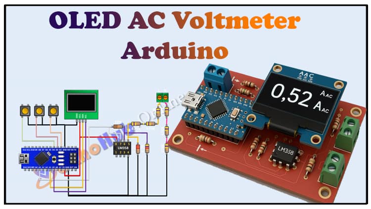
OLED AC Voltmeter Arduino Project | 5-Step DIY Electronics Guide
This OLED AC Voltmeter Arduino Project is a practical DIY electronics build that measures AC voltage and displays it on an OLED screen. The OLED AC Voltmeter Arduino Project uses Arduino Nano, LM358 IC, and resistors for accurate scaling. Anyone can follow this OLED AC Voltmeter Arduino Project with circuit diagram, step-by-step guide, and coding instructions.
Introduction
Measuring AC voltage is a core requirement in electrical and electronics work. While commercial digital voltmeters are common, building your own not only deepens understanding but also gives flexibility in customization.
This OLED AC Voltmeter Arduino Project allows you to measure AC mains voltage safely and display the readings on a bright OLED display. The heart of this project is an Arduino Nano, which processes the scaled signal from an LM358 op-amp circuit. The resistive divider and filter network ensure the voltage fed to Arduino is within its ADC input range.
By completing this project, you will:

Learn how AC voltage scaling circuits work.
Interface an LM358 with Arduino for analog signal processing.
Use an OLED display for clear, real-time readings.
Build a compact, DIY AC voltmeter suitable for lab or home use.
Materials for the Project (OLED AC Voltmeter)
| Component | Quantity | Description | Buy Link |
|---|---|---|---|
| Arduino Nano | 1 | Microcontroller board | Buy Link |
| OLED Display (0.96″ I2C) | 1 | For displaying voltage | Buy Link |
| LM358 IC | 1 | Dual Op-Amp for scaling | Buy Link |
| 2.2kΩ Resistor | 1 | Voltage divider resistor | Buy Link |
| 4.7kΩ Resistor | 1 | Voltage divider resistor | Buy Link |
| 10kΩ Resistor | 1 | Feedback & divider | Buy Link |
| 470kΩ Resistors | 6 | High value divider network | Buy Link |
| 2-Pin Terminal Block | 2 | For AC input & connections | Buy Link |
| Perf Board | 1 | Prototyping board | Buy Link |
| Jumper Wires | As needed | For connections | Buy Link |
Useful Tools
| Tool | Quantity | Purpose / Notes | Click & Buy |
|---|---|---|---|
| Soldering Iron Kit | 1 | For making permanent connections | Click & Buy |
| Solder Wire (60/40, 0.8mm) | 1 | Electrical soldering | Click & Buy |
| Wire Stripper & Cutter | 1 | Stripping jumper wires | Click & Buy |
| Mini Screwdriver Set | 1 | For module and relay terminal screws | Click & Buy |
| Multimeter | 1 | Testing voltages and continuity | Click & Buy |
| Hot Glue Gun (optional) | 1 | Securing components in place | Click & Buy |
| Small Pliers | 1 | Holding and bending wires | Click & Buy |
| Heat Shrink Tubing Set | 1 | Insulating exposed wires | Click & Buy |
Download Circuit Diagram

Circuit Diagram & Explanation
The circuit can be broken down into three main sections:
1. AC Voltage Scaling Network
AC mains voltage (110V/220V depending on your region) is reduced using a resistive divider made with 470kΩ resistors in series.
This brings the high AC down to a safer low level suitable for the LM358 op-amp input.
2. Signal Conditioning (LM358)
The LM358 is used to buffer and scale the voltage.
Since Arduino can only read positive voltages (0–5V), the op-amp ensures the scaled signal stays within the ADC range.
Filtering capacitors (optional) can smooth noise for stable readings.
3. Arduino & OLED Display
Arduino Nano reads the scaled AC waveform using its ADC pins.
The RMS value is calculated in software.
The final voltage value is displayed on the OLED screen using I2C communication.
⚠️ Safety Note: The AC input is directly connected through resistors. Handle with care, keep connections insulated, and avoid touching live wires during operation. For higher safety, an isolated transformer can be added.
Step-by-Step Guide to Building the OLED AC Voltmeter Arduino Project
Step 1: Gather Components
Collect all parts listed in the BOM. Double-check resistor values with a multimeter to avoid scaling errors.
Step 2: Assemble the Voltage Divider
Connect six 470kΩ resistors in series.
Add the 2.2kΩ and 4.7kΩ resistors to fine-tune scaling.
Connect the divider output to the input of the LM358 op-amp.
Step 3: Wire the LM358
Use the LM358 in a buffer/amplifier configuration.
Ensure the op-amp output does not exceed 5V peak.
Connect the op-amp output to A0 pin of Arduino Nano.
Step 4: Connect the OLED Display
Connect SDA → A4 and SCL → A5 on Arduino Nano.
VCC → 5V, GND → GND.
Step 5: Upload the Arduino Code
Use Arduino IDE.
Install the Adafruit SSD1306 and GFX libraries for OLED.
Upload code that reads AC voltage, calculates RMS, and displays the result.
Arduino Code
Applications
DIY lab instruments.
Household voltage monitoring.
Educational projects for learning about AC measurement.
Integration with IoT (logging data online with ESP8266/ESP32).
FAQs
Q1. Can I use a different op-amp instead of LM358?
Yes, but ensure it can handle single-supply operation and input range down to ground.
Q2. Is this project safe for direct mains connection?
With proper resistor scaling and insulation, it works. For extra safety, use a small isolation transformer.
Q3. Can I display voltage in larger fonts?
Yes, adjust the OLED library text size function (setTextSize()).
Q4. How accurate is this voltmeter?
Accuracy depends on resistor tolerances, op-amp offset, and calibration. Typically ±2–3%.
Q5. Can I expand this to measure current and power too?
Yes, by adding a current sensor like ACS712 and modifying code.