

Introduction
A PIR Motion Sensor Radar brings together compact hardware and clever signal interpretation to visualize movement in a simple radar-style layout.Building an embedded motion alert system is a fantastic way to dive into Arduino Nano 33 IoT projects and understand infrared-based motion sensing. This guide walks you through creating a simple DIY smart security system using a passive infrared (PIR) sensor to detect movement.
The core of this project is transforming simple motion data into a captivating radar-style animation displayed on an OLED SSD1306 graphical display. This combination of low-power motion tracking and effective visualization makes for a practical and engaging experiment in microcontroller-based security projects.
Overview PIR Motion Sensor Radar
The PIR Motion Sensor Radar offers a practical way to display human movement on a compact OLED display using straightforward microcontroller logic. When infrared energy changes within the sensing zone, the Arduino interprets the data and maps it visually on the screen.
The OLED SSD1306’s high contrast makes the radar sweep clean and easy to analyze. This setup is ideal for beginners experimenting with motion-based visualization while still providing enough depth for advanced prototyping. It blends simplicity with capability, allowing hobbyists to explore radar-like feedback without complex RF circuits or expensive modules.
Components Required
| Quantity | Component | Description | Buy Link |
|---|---|---|---|
| 1 | Arduino Nano 33 IoT | Microcontroller with built-in WiFi & I2C support | Buy Link |
| 1 | AM312 PIR Motion Sensor | Detects motion using infrared radiation | Buy Link |
| 1 | SSD1306 128×64 OLED Display (I2C) | Displays radar animation and alerts | Buy Link |
| 1 | Breadboard | For easy wiring and prototyping | Buy Link |
| 1 | Micro-USB Cable | To power and program the Arduino | Buy Link |
| Few | Jumper Wires | For connections | Buy Link |
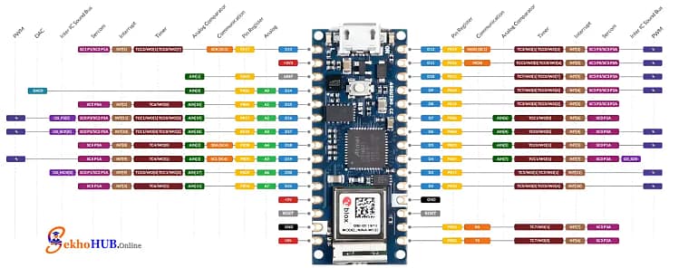
Arduino Nano 33 IoT
The Arduino Nano 33 IoT is a compact yet powerful board with ARM Cortex-M0+, WiFi, Bluetooth, and built-in IMU support, making it ideal for modern connected projects. Its low power consumption and excellent I2C compatibility make it well-suited for sensor-driven prototypes. Learn more
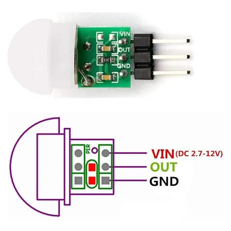
AM312 PIR Motion Sensor
The AM312 PIR Motion Sensor is an ultra-small, highly efficient infrared detector that identifies human movement by sensing changes in IR radiation. It offers a stable output, low power usage, and a plug-and-play interface for microcontrollers. Ideal for compact automation and security systems. Learn more
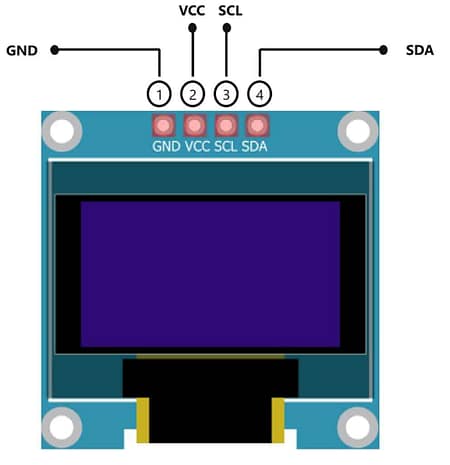
SSD1306 128×64 (I2C)
The SSD1306 128×64 OLED Display provides crisp monochrome graphics with minimal power draw, making it perfect for embedded visual feedback. Using I2C communication, it integrates smoothly with most microcontrollers and supports dynamic animations like radar sweeps. Learn more
Circuit Diagram
[Insert circuit diagram image here]
Build Guide Step-by-Step
Step 1. Prepare the Arduino Nano 33 IoT
Place the Arduino Nano 33 IoT onto the breadboard and ensure it is firmly seated so all pins are accessible for wiring.
Step 2. Power the PIR Sensor
Connect the PIR sensor’s VCC pin to the Arduino’s 3.3V pin.
Now connect the PIR sensor’s GND pin to the Arduino’s GND pin.
Step 3. Connect the PIR Output
Attach the PIR sensor’s OUT pin to the Arduino D2 pin so the board can read motion signals.
Step 4. Wire the OLED Display Power
Connect the OLED VCC pin to the Arduino 3.3V pin.
Then connect the OLED GND pin to the Arduino GND pin.
Step 5. Connect OLED I2C Lines
Wire the OLED’s SDA pin to the Arduino’s A4 pin.
Wire the OLED’s SCL pin to the Arduino’s A5 pin to complete I2C communication.
Step 6. Verify Common Ground
Ensure all modules—PIR sensor, OLED display, and Arduino—share the same ground for stable operation.
Step 7. Secure All Connections
Tighten jumper wires, avoid loose pins, and make sure the PIR is positioned with a clear field of view.
Step 8. Upload the Arduino Code
Connect the Arduino Nano 33 IoT to your PC via USB.
Select the board and port in the IDE, then upload your radar visualization sketch.
Step 9. Test the Radar Movement
After the upload completes, power the board and wave your hand in front of the PIR sensor to confirm the radar animation responds to motion.
| Arduino Nano 33 IoT Pin | PIR Sensor Pin | OLED Pin | Description |
|---|---|---|---|
| D2 | OUT | – | PIR output signal to Arduino |
| 3.3V | VCC | VCC | Power supply (both PIR & OLED use 3.3V) |
| GND | GND | GND | Common ground |
| – | – | SDA (A4) | I2C data line for OLED |
| – | – | SCL (A5) | I2C clock line for OLED |
Arduino Code.
#include <Adafruit_GFX.h>#include <Adafruit_SSD1306.h>#include <math.h>#define SCREEN_WIDTH 128#define SCREEN_HEIGHT 64Adafruit_SSD1306 display(SCREEN_WIDTH, SCREEN_HEIGHT, &Wire, -1);const int pirPin = 2;float angle = 0; // radar sweep angleconst int radarRadius = 30;const int centerX = SCREEN_WIDTH/2;const int centerY = SCREEN_HEIGHT/2;void setup() {Serial.begin(9600);pinMode(pirPin, INPUT);if(!display.begin(SSD1306_SWITCHCAPVCC, 0x3C)){Serial.println("SSD1306 allocation failed");for(;;);}display.clearDisplay();display.display();}void loop() {bool motionDetected = digitalRead(pirPin);display.clearDisplay();if(!motionDetected){// --- Radar animation ---// Draw radar circledisplay.drawCircle(centerX, centerY, radarRadius, SSD1306_WHITE);display.drawCircle(centerX, centerY, radarRadius-5, SSD1306_WHITE);// Draw sweeping lineint x = centerX + radarRadius * cos(angle);int y = centerY + radarRadius * sin(angle);display.drawLine(centerX, centerY, x, y, SSD1306_WHITE);// Increment sweep angleangle += 0.1; // speed of sweepif(angle > 2*3.14159) angle = 0;// Draw radar centerdisplay.fillCircle(centerX, centerY, 2, SSD1306_WHITE);} else {// --- Motion detected ---display.setTextSize(2);display.setTextColor(SSD1306_WHITE);display.setCursor(5, SCREEN_HEIGHT/2 - 10);display.println("Motion!");}display.display();delay(30); // controls smoothness}
Applications
Compact IoT security systems
Smart home automation
Human presence monitoring
Educational microcontroller demonstrations
Portable motion visualization devices
FAQs
What is the difference between PIR motion sensor and radar?
A PIR sensor detects changes in infrared heat from humans or animals, while radar detects motion using radio waves and can sense movement through some materials.
What is a PIR motion sensor?
A PIR motion sensor identifies movement by detecting variations in infrared radiation within its field of view.
What is a PIR used for?
It’s commonly used in security systems, automatic lighting, alarms, and presence detection applications.
What is a radar motion sensor?
A radar motion sensor uses high-frequency radio waves to measure motion, speed, and distance of moving objects.
How far can a PIR sensor detect?
Most PIR sensors detect motion between 3 to 10 meters, depending on the lens design and environment.
What are the three types of radar?
The main types are Continuous Wave (CW), Pulse Ra
Conclusion
Combining the PIR sensor with an OLED display transforms simple motion detection into a visually appealing radar-style experience. The Arduino Nano 33 IoT processes incoming signals quickly, enabling real-time feedback and smooth animations. This project is both educational and practical, offering insights into PIR, Radar, Arduino, SSD1306, Nano 33, IoT, OLED, Motion, Sensor, and Display interactions. Whether you’re exploring embedded graphics or building an automation prototype, this setup provides a reliable and expandable foundation.