

Powerful DIY IR Sensor with Relay for Smart in 3 Easy Steps
If you’re looking for a beginner-friendly electronics project, building a DIY IR sensor with a 5V relay is a great choice. This step-by-step guide shows how to assemble a DIY IR using an HW-201 IR proximity sensor, a 5V relay module, and a simple 5V power supply. You’ll learn how the DIY IR sensor detects objects, how the relay activates connected loads, and how to wire it correctly for reliable performance. With our instructions, anyone can create a DIY IR sensor that controls lights, fans, or alarms automatically. Whether you want a home automation upgrade or a simple object detection system, this DIY IR project is affordable and effective. Follow along to build your own DIY IR today.
Introduction.
When I first started experimenting with automation circuits over 10 years ago, one of the simplest yet most useful projects I built was a DIY IR sensor with a relay. It’s small, inexpensive, and can control anything from a table lamp to a security siren—all triggered by the wave of your hand or the movement of an object.
In this guide, I’ll walk you through creating your own using an HW-201 IR proximity sensor, a 5V relay module, and a few jumper wires. No programming is required—it’s pure plug-and-play electronics.
Materials for the Project
| No. | Component | Specification | Quantity | Click & Buy |
|---|---|---|---|---|
| 1 | HW-201 IR Proximity Sensor | 3.3V–5V, adjustable | 1 | Click & Buy |
| 2 | 5V Relay Module | 1-Channel, 10A | 1 | Click & Buy |
| 3 | 5V Power Supply | DC Adapter or USB | 1 | Click & Buy |
| 4 | Jumper Wires | Male-to-Male/Female | 4–6 | Click & Buy |
| 5 | Load Device (Light/Fan/Alarm) | AC or DC load | 1 | Click & Buy |
| 6 | Breadboard (optional) | 830 tie points | 1 | Click & Buy |
Useful Tools
| Tool | Quantity | Purpose / Notes | Click & Buy |
|---|---|---|---|
| Soldering Iron Kit | 1 | For making permanent connections | Click & Buy |
| Solder Wire (60/40, 0.8mm) | 1 | Electrical soldering | Click & Buy |
| Wire Stripper & Cutter | 1 | Stripping jumper wires | Click & Buy |
| Mini Screwdriver Set | 1 | For module and relay terminal screws | Click & Buy |
| Multimeter | 1 | Testing voltages and continuity | Click & Buy |
| Hot Glue Gun (optional) | 1 | Securing components in place | Click & Buy |
| Small Pliers | 1 | Holding and bending wires | Click & Buy |
| Heat Shrink Tubing Set | 1 | Insulating exposed wires | Click & Buy |
Understanding the DIY IR Sensor with Relay
An IR sensor detects objects based on reflected infrared light. The HW-201 IR module emits infrared light via an IR LED and detects the reflection with a photodiode. When something comes close, the sensor’s output changes state, which we use to trigger a relay.
The relay acts as an electronic switch, controlling high-power devices while isolating them from the low-voltage control circuit.
Key Features of the HW-201 IR Proximity Sensor
Detection Range: Adjustable from ~2cm to ~30cm.
Operating Voltage: 3.3V to 5V.
Adjustable Sensitivity: Onboard potentiometer.
Output Type: Digital (HIGH/LOW).
Applications of This Project
Automatic light switching in hallways or cupboards.
Touchless control for fans or pumps.
The security alarm triggers when someone approaches.
Counting systems for objects on a conveyor.
Download Circuit Diagram

Circuit Diagram Explanation
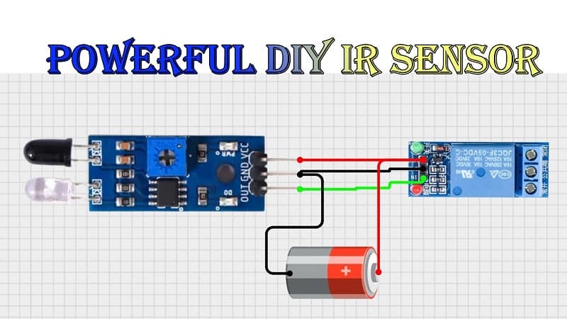
Connections:
HW-201 IR Sensor
VCC → 5V power supply
GND → Ground
OUT → Relay module IN pin
Relay Module
VCC → 5V power supply
GND → Ground
IN → From IR sensor output
COM & NO → Series connection to load and power source
Working:
When an object is detected, HW-201 sends a HIGH or LOW signal (depending on configuration) to the relay.
The relay energizes and closes the circuit for the connected load.
The load turns ON automatically without manual switching.
Step-by-Step Build Guide
Step 1 – Preparing the Components
Gather the HW-201 IR sensor, 5V relay module, jumper wires, and power supply.
Optionally, use a breadboard for prototyping.
Step 2 – Wiring the IR Sensor to Relay
Connect HW-201 OUT → Relay IN.
Connect power and ground pins for both modules.
Step 3 – Connecting the Load
Wire your AC or DC device in series with the COM and NO contacts of the relay.
Ensure relay ratings match your load voltage and current.
Step 4 – Testing the Setup
Power up the system.
Move your hand or an object in front of the IR sensor.
Listen for the relay click and observe the load turning ON.
Pro Tips for Reliable Operation
Adjust the potentiometer to fine-tune detection distance.
Use a stable 5V supply for consistent performance.
If using AC loads, ensure all wiring is insulated for safety.
FAQs
Q1: Can I increase the detection range beyond 30 cm?
Not with the HW-201—for longer range, use an ultrasonic sensor.
Q2: Can I use this outdoors?
Yes, but place the sensor in a weatherproof enclosure.
Q3: Will sunlight affect detection?
Yes, direct sunlight can cause false triggers; use IR filters or shade.
Q4: Can this work without Arduino?
Yes, this design works standalone without any microcontroller.
Q5: Can I use a 12V relay instead of 5V?
Yes, but match it with a 12V power supply and adjust wiring accordingly.