

Simple IR-Controlled On/Off Relay Switch Project
Remote control technology is not just for televisions anymore. With the right components, you can control electrical devices from a distance using a regular infrared (IR) remote. In this project, we will build a simple IR-controlled on/off relay switch that can be used to operate home appliances, lights, or other electronic devices.
This circuit is straightforward, cost-effective, and uses easily available components. It is a great project for hobbyists, students, and anyone interested in automation.
How the Circuit Works
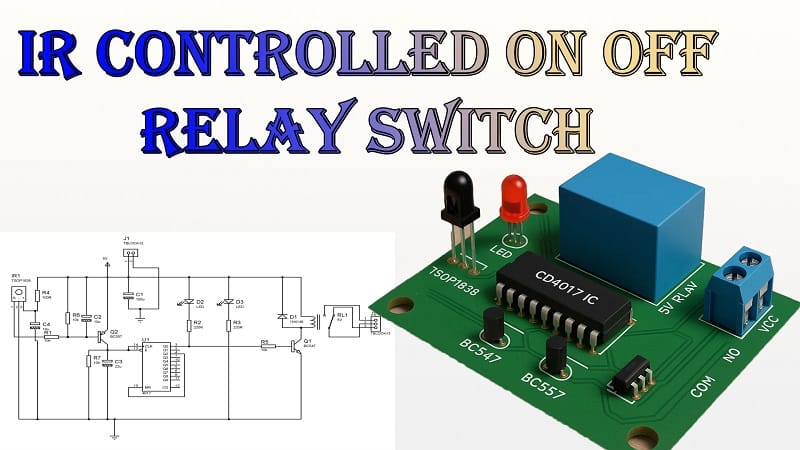
This IR-controlled relay switch is built around a TSOP1838 IR sensor, a CD4017 decade counter IC, and two transistors (BC547 and BC557) to drive a 5V relay.
When you press a button on the IR remote, the TSOP1838 detects the modulated IR signal and converts it into an electrical pulse. The CD4017 IC acts as a toggle control. Each valid signal from the remote changes the relay state—turning the connected device ON or OFF.
The relay allows you to control high-voltage appliances with the low-voltage control signal from the circuit.
Materials for the Project
| S.No | Component Name | Specification / Value | Quantity |
| 1 | CD4017 IC | Decade Counter | 1 |
| 2 | TSOP1838 IR Sensor | 38 kHz Receiver | 1 |
| 3 | BC547 Transistor | NPN | 1 |
| 4 | BC557 Transistor | PNP | 1 |
| 5 | 1N4148 Diode | Switching Diode | 1 |
| 6 | LED | 5 mm (Red/Green) | 2 |
| 7 | Capacitor | 10 µF, 25 V Electrolytic | 2 |
| 8 | Capacitor | 22 µF, 25 V Electrolytic | 1 |
| 9 | Capacitor | 100 µF, 25 V Electrolytic | 1 |
| 10 | Resistor | 100Ω, 1/4W | 1 |
| 11 | Resistor | 220Ω, 1/4W | 2 |
| 12 | Resistor | 10kΩ, 1/4W | 4 |
| 13 | 2-Pin Terminal Block | PCB Mount | 1 |
| 14 | 3-Pin Terminal Block | PCB Mount | 1 |
| 15 | 5V Relay | SPDT | 1 |
| 16 | Perf Board | General Purpose PCB | 1 |
| 17 | Jumper Wires | Flexible/Solid Core | As needed |
Download Circuit Diagram

The TSOP1838 IR sensor receives commands from any standard remote that transmits at 38 kHz. Its output goes to the CD4017, which works as a toggle flip-flop in this configuration.
Step-by-Step Working Principle
1. IR Signal Reception
When you press a button on the remote, it sends an IR pulse. The TSOP1838 sensor detects this signal and outputs a short active-low pulse.
2. Signal Processing with CD4017
The CD4017 is a decade counter, but in this project, it is wired to act as a toggle switch. Each pulse from the TSOP1838 advances the CD4017’s output, switching between two states.
3. Transistor Driver Stage
- The BC547 (NPN) transistor acts as a signal amplifier for the relay control.
- The BC557 (PNP) transistor is part of the drive circuit that helps energize the relay coil without overloading the IC.
4. Relay Switching
When the relay coil is energized, the contacts change position, turning the connected appliance ON. Pressing the same remote button again deactivates the relay, switching the appliance OFF.
5. LED Indicators
Two LEDs are used:
- Power LED: Indicates that the circuit is powered.
- Status LED: Shows when the relay is active (ON).
Assembly Instructions
Step 1 – Component Placement
- Place the CD4017 IC at the center of the perf board for easier wiring.
- Position the TSOP1838 IR sensor at one edge to face the remote control.
- Arrange the transistors and relay close to the output terminal block.
Step 2 – Wiring
- Connect the TSOP1838 output to the clock input of the CD4017.
- Wire the CD4017’s Q0 and Q1 outputs for toggle operation.
- Add the transistors in the relay driver stage, following the circuit diagram.
- Connect the relay output to the 2-pin terminal block for appliance control.
Step 3 – Power Supply
- The circuit works on a 5V DC supply. You can use a regulated adapter or a USB power source.
- Make sure the power connections are solid to avoid reset glitches.
Step 4 – Testing
- Power up the circuit.
- Point a remote at the TSOP1838 and press a button.
- The relay should click, and the status LED should turn ON.
- Press the button again, and the relay should turn OFF.
Applications
- Home appliance control—Operate lights, fans, or other electronics from your couch.
- DIY automation projects—control small gadgets in your workshop remotely.
- Smart home integration – Combine with other circuits for a complete remote-control system.
- Educational projects – Demonstrates IR communication and relay control principles.
Advantages of This Design
- Low cost—uses common and inexpensive components.
- Easy to build—no programming required, purely hardware-based.
- Reliable operation—works with most IR remotes.
- Compact size—fits easily on a small perf board.
Tips for Better Performance
- Use a stable 5V power source for consistent operation.
- Keep the TSOP1838 sensor facing the remote for better reception.
- Avoid placing the circuit near strong sunlight or fluorescent lamps, as these can interfere with IR reception.
- Use proper insulation when controlling AC appliances via the relay.
Final Thoughts
This simple IR-controlled on/off relay switch is an excellent beginner-friendly electronics project. It allows you to operate any appliance remotely without complex coding or microcontroller programming. The use of a CD4017 decade counter and TSOP1838 IR sensor makes the circuit reliable and easy to understand.
By following the step-by-step guide above, you can build this project in an afternoon and enjoy the convenience of controlling your devices with just a click of a remote.