
Simple Over/Under Voltage Protection Circuit Using LM393
[Sekhohub.online]
Voltage fluctuations can damage sensitive electronic appliances. Whether you’re powering a DC fan, LED strip, battery charger, or controller, it’s essential to protect your system from over-voltage and under-voltage conditions.
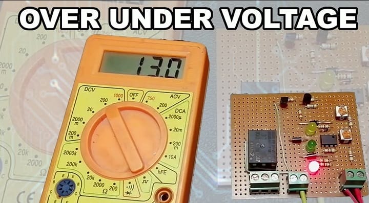
In this project, we will build a simple over/under voltage protection circuit using the LM393 comparator IC, BC547 and BC557 transistors, and a 12V relay.
This circuit automatically cuts off power to the load when the voltage goes below or above safe limits.

Materials for the Project
- 1x LM393 IC
- 1x BC547 TRANSISTOR
- 1x BC557 TRANSISTOR
- 2x 5K VARIABLE RESISTORS
- 4x 1N4007 DIODES
- 1x 3V ZENER DIODE
- 3x LEDs (RED, GREEN, AND YELLOW )
- 5x 1K RESISTORS
- 3x 4.7K RESISTORS
- 2x 10K RESISTORS
- 1x 12V RELAY
- 2x 2-PIN TERMINAL BLOCK
- 1x 3-PIN TERMINAL BLOCK
- VERO BOARD
- JUMPER WIRES
Circuit Overview
The LM393 is a dual comparator IC that compares two input voltages and changes its output accordingly.
We’ll use:
Comparator 1 to detect over-voltage
Comparator 2 to detect under-voltage
Each comparator is connected to a voltage divider and reference zener diode, and its output drives a transistor that controls the relay.
⚙️ How It Works
The input voltage is divided using resistors and compared with Zener reference voltages.
If the voltage goes below the under-voltage threshold, the comparator output goes high → the transistor turns off → the relay turns off → the load is disconnected.
If the voltage goes above the over-voltage threshold, the comparator output also goes high → the transistor turns off → the relay turns off.
Only when voltage is within a safe range, the output of both comparators is low, the transistor conducts, the relay is ON, and the load is connected.
️ Threshold Adjustment
You can set:
Under-voltage cut-off point using the first potentiometer
Over-voltage cut-off point using the second potentiometer
Typical settings for a 12V system:
Under-voltage cut-off: ~10.5V
Over-voltage cut-off: ~14.5V
Testing Steps
Power the circuit with a variable DC supply.
Slowly increase the voltage from 0V to 15V and observe when the relay clicks ON and OFF.
Tune the potentiometers to set your exact cut-off values.
Add a 12V LED or bulb as a load to verify switching.
Why Use LM393?
Low power consumption
Built-in dual comparator
Fast switching time
Open-collector output (perfect for transistor control)
Applications
✅ Battery over/under-voltage protection
✅ Solar charge controllers
✅ DC power supplies
✅ Industrial DC equipment safety
✅ Smart home power systems
⚠️ Safety Notes
Always use a diode (1N4007) across the relay coil to suppress back EMF.
Use the correct relay rating for your load (DC or AC).
For higher current loads, use a relay driver with a heatsink.
Video Tutorial
Download Circuit Diagram

✅ Conclusion
With just an LM393, a couple of transistors, and a relay, you can build a compact and efficient voltage protection circuit for any 12V system. It’s low-cost, easy to assemble, and highly reliable.
For more DIY electronics circuits and tutorials, keep visiting SekhoHub.online—Pakistan’s growing platform for electronics learners and makers.