

Smart & Safe DIY Fire Detection System in 3 Steps
Build your own Smart & Safe DIY Fire Detection System with just 3 powerful steps using the KY-026 Infrared Flame Sensor, a 5V Relay Module, and a simple 5V Power Supply. This beginner-friendly guide explains the working principle, wiring, and testing process in detail, so you can protect your home with confidence.
We’ll cover the complete bill of materials, circuit diagram explanation, and a clear step-by-step setup process. Whether you’re new to electronics or an experienced hobbyist, this project is easy to follow and uses readily available components. You’ll learn how to detect fire using infrared technology and trigger a relay for alarms or automatic response systems. Create a reliable and affordable solution for fire detection, enhance your safety, and gain hands-on experience with sensor-based electronics.
Introduction.
Fire safety isn’t just for large buildings—even your home workshop can benefit from a reliable early warning system. Today, we’ll build a Smart & Safe DIY Fire Detection System using the KY-026 Infrared Flame Sensor, a 5V Relay Module, and a few jumper wires.
I’ve been working with electronics for over a decade, and trust me—this is one of the simplest yet most effective safety projects you can make. It’s perfect for Arduino enthusiasts, students, or anyone interested in practical electronics.
How the DIY Fire Detection System Works
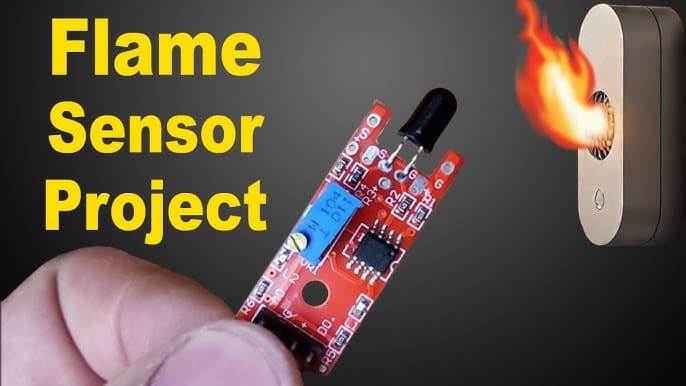
The KY-026 infrared flame sensor detects infrared light emitted by flames. Once it senses fire, it sends a signal to the 5V relay module. The relay can then activate an alarm or siren or even cut off power to dangerous equipment.
This system can be standalone or integrated into IoT platforms for remote alerts.
Materials for the Project (DIY Fire Detection)
| Component | Quantity | Description/Notes | Click & Buy |
|---|---|---|---|
| KY-026 Infrared Flame Sensor | 1 | Detects fire by sensing IR light | Click & Buy |
| 5V Relay Module | 1 | Controls external devices | Click & Buy |
| 5V DC Power Supply | 1 | Powers the system | Click & Buy |
| Jumper Wires (Male-Female) | 5–6 | For connections | Click & Buy |
| Breadboard (optional) | 1 | For prototyping | Click & Buy |
| Buzzer or Alarm (optional) | 1 | Audible alert device | Click & Buy |
| Indicator LED (optional) | 1 | Visual alert | Click & Buy |
| Resistors (220Ω for LED) | 1 | LED current limiting | Click & Buy |
Useful Tools (DIY Fire Detection)
| Tool | Quantity | Purpose / Notes | Click & Buy |
|---|---|---|---|
| Soldering Iron Kit | 1 | For making permanent connections | Click & Buy |
| Solder Wire (60/40, 0.8mm) | 1 | Electrical soldering | Click & Buy |
| Wire Stripper & Cutter | 1 | Stripping jumper wires | Click & Buy |
| Mini Screwdriver Set | 1 | For module and relay terminal screws | Click & Buy |
| Multimeter | 1 | Testing voltages and continuity | Click & Buy |
| Hot Glue Gun (optional) | 1 | Securing components in place | Click & Buy |
| Small Pliers | 1 | Holding and bending wires | Click & Buy |
| Heat Shrink Tubing Set | 1 | Insulating exposed wires | Click & Buy |
Download Circuit Diagram

Circuit Diagram Explanation (DIY Fire Detection)
The circuit is straightforward:
VCC of KY-026 → 5V Power Supply
GND of KY-026 → GND
Signal Pin of KY-026 → IN Pin of 5V Relay
Relay VCC → 5V Power Supply
Relay GND → GND
Relay Output → Connected to alarm or other safety device
When a flame is detected:
KY-026 outputs a HIGH signal.
The relay is triggered.
The alarm (buzzer or siren) activates immediately.
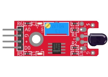
KY-026 Pinout.
| Pin | Label | Function |
|---|---|---|
| 1 | A0 | Analog output—voltage changes with flame intensity. |
| 2 | G or GND | Ground connection. |
| 3 | D0 | Digital output—HIGH or LOW based on the set threshold. |
| 4 | VCC | Power supply (3.3V–5V). |
Step-by-Step Guide (DIY Fire Detection)
Step 1 – Assemble the Components
Place the KY-026 flame sensor on the breadboard.
Connect jumper wires from KY-026 to the relay module.
Wire the relay module to the power supply.
Step 2 – Connect the Output Device
Attach a buzzer, siren, or LED to the relay output.
If you want to control AC devices, use the relay’s normally open (NO) contact for safety.
Step 3 – Test the System
Power up the circuit.
Use a lighter or candle at a safe distance to test flame detection.
Adjust the KY-026’s sensitivity using its onboard potentiometer.
Safety Tips
Never bring large flames near sensitive electronics.
Use only small controlled sources like a candle for testing.
Ensure your relay is properly rated for the device you’re controlling.
Applications
Home fire alarm systems
Workshop equipment auto-shutdown
Smart home IoT fire alert integration
School electronics safety demonstrations
FAQs
Q1: Can I use this system without a microcontroller?
Yes, the KY-026 directly triggers the relay without requiring an Arduino.
Q2: How far can the sensor detect a flame?
Typically up to 80 cm, depending on flame size and sensitivity setting.
Q3: Can it work outdoors?
Yes, but avoid direct sunlight, as it may cause false triggers.
Q4: Can I connect it to Wi-Fi for alerts?
Yes, integrate with ESP8266/ESP32 for IoT notifications.