

Temperature Data Logger With SD Card Module | SekhoHub |
Hi friends, in this video I’m going to make a temperature logger using Arduino.

Let’s see the connections of the project.
- First connect Arduino.

- Then connect a two-pin terminal block and connect its one pin to five full pins of the Arduino and its other pin to ground.

- Then connect a 16×2 LCD and connect its VCC pin to 54 pin of the Arduino. It’s grounded pin to ground, its SDA pin to the A4 pin of the Arduino, and its SDL pin to the A5 pin of the Arduino.

- Then connect a push button and connect one of its pins to the D3 pin of the Arduino and its other pin to ground.

- Then connect another push button and connect its one pin to the D4 pin of the Arduino and its other pin to ground.

- Now connect another push button and connect its one pin to the D5 pin of the Vino and its other pin to ground.
- Now connect the temperature sensor and connect its VCC pin to the 5f pin of the Arduino, its ground pin to ground, and its data pin to the D2 pin of the Arduino.

- Now connect the SD card module and connect its VCC pin to fivefold pin of ino, its gro ground pin to ground, and its CS pin to the D10 pin of Arduino. It’s the SCK pin to D13 pin of the Arduino. It’s the MOSI pin to the D11 pin of the Arduino, and it’s the opening to D12 of the Arduino.


So we have completed all the connections; now let’s upload the code to Arduino and test the project.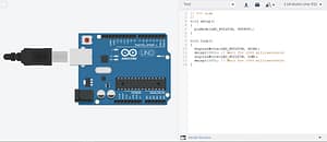
![]()
So that’s it for today’s project. I hope you have enjoyed this video. For more projects like that, stay tuned, and I will see you in the next project.
Temperature Logger Setting