

5 Simple Steps to Build a TTP223 Touch Sensor Module Capacitive Touch Buzzer Alarm
The TTP223 Touch Sensor Module Capacitive Touch Buzzer Alarm is a simple yet effective project that introduces you to capacitive touch sensing. Using the TTP223 module, a 5V active buzzer, and a basic power supply, you can create a touch-activated alarm system without mechanical switches. The TTP223 Touch Sensor Module Capacitive Touch Buzzer Alarm works by detecting finger contact and triggering a buzzer sound instantly.
This project is perfect for beginners learning electronics, DIY enthusiasts experimenting with touch-based interfaces, or students exploring sensor applications. The TTP223 Touch Sensor Module Capacitive Touch Buzzer Alarm can be built in just minutes using affordable components. With a clear wiring diagram, step-by-step guide, and explanation, this tutorial helps you understand the working principle of capacitive sensors. Start building your own TTP223 Touch Sensor Module Capacitive Touch Buzzer Alarm today and add smart touch control to your projects.
Introduction
Mechanical switches are everywhere, but they wear out over time. Capacitive touch technology is a modern alternative that lets you activate devices with just a tap of your finger. One of the most popular low-cost modules for this purpose is the TTP223 capacitive touch sensor.
In this project, we’ll use the TTP223 Touch Sensor Module to build a Capacitive Touch Buzzer Alarm. With a simple circuit, you can make a buzzer sound whenever you touch the sensor pad. This project is beginner-friendly and can be completed in under 30 minutes.
Working Principle of the Alarm
The TTP223 sensor works by detecting changes in capacitance when a finger touches its sensing pad.
No touch → OUT pin remains LOW.
Touch detected → OUT pin goes HIGH (3.3V–5V).
This HIGH signal is fed to a buzzer module, producing sound.
Thus, a simple touch is enough to trigger the alarm.

Pinout of TTP223 Touch Sensor
VCC → 2.0V – 5.5V
GND → Ground
OUT → Digital output signal
Bill of Materials (BOM Table with Click & Buy Links)
Circuit Diagram Explanation
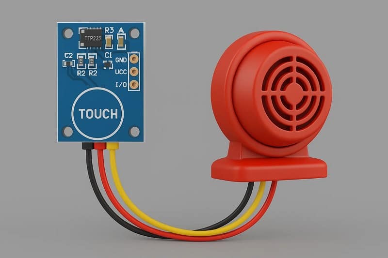
Connect VCC of TTP223 → +5V supply
Connect GND of TTP223 → GND of supply
Connect OUT of TTP223 → Positive pin of buzzer
Connect Negative pin of buzzer → GND
➡️ When you touch the sensor pad, the buzzer activates. Release your finger, and the buzzer stops.
Step-by-Step Guide
Step 1: Gather Components
Collect the TTP223 module, buzzer, breadboard, and jumper wires.
Step 2: Power the Sensor
Connect the VCC and GND of the TTP223 module to a regulated 5V supply.
Step 3: Connect the Output
Attach the OUT pin to the positive terminal of the buzzer.
Step 4: Complete the Circuit
Connect the negative buzzer pin to ground.
Step 5: Test the Alarm
Touch the sensor pad – the buzzer should sound. Release – it should stop.
Applications
Touch-based door alarm system
Desk bell without switches
Silent alarm trigger in security systems
Educational project for learning capacitive sensors
Safety Tips
Use a regulated 5V power supply.
Avoid powering directly from unregulated sources.
Always check wiring before powering.
Authoritative References (Outbound Links)
FAQs
1. Can I power the TTP223 with 3.3V?
Yes, it works with 2V–5.5V.
2. Can I use a passive buzzer?
Yes, but you’ll need an oscillator signal (like Arduino PWM).
3. Can I replace the buzzer with an LED?
Yes, the OUT pin can drive small loads like LEDs.
4. Is the sensor durable?
Yes, capacitive sensors have no moving parts and last long.
5. Can I expand this to multiple buzzers?
Yes, but ensure the current rating is supported.