

This article explains how to build a Two Channel Time Controlled Relay circuit using Arduino, relays, RTC, LCD, transistors, and supporting components. The Two Channel Time Controlled Relay is a hardware-based automation project that switches two devices ON and OFF at specific times. The Two Channel Time Controlled Relay project uses a real-time clock for accurate scheduling and an LCD for display. The Two Channel Time Controlled Relay circuit includes relays controlled by BC547 transistors, diodes, and resistors.
This Two Channel Time Controlled Relay project provides a complete bill of materials with buy links. The Two Channel Time Controlled Relay circuit diagram and connections are explained in detail. The Two Channel Time Controlled Relay project helps beginners learn relay interfacing with Arduino. Building a Two Channel Time Controlled Relay is simple and efficient with basic electronic components.
Introduction
Automation has become an essential part of modern electronics. One of the simplest yet powerful automation circuits is a Two Channel Time Controlled Relay, which allows you to control two separate loads (appliances, devices, or systems) based on a time schedule.
This project is strictly hardware-focused. It uses an Arduino board, an RTC (real-time clock) module for accurate timekeeping, an LCD to display information, and two relays controlled by transistors and supporting components.
The Two Channel Time Controlled Relay is particularly useful for controlling devices where manual switching is not desirable, or when precise timing is required.
Materials for the Project
| S.No | Component | Quantity | Description | Buy Link |
|---|---|---|---|---|
| 1 | Arduino Uno/Nano | 1 | Microcontroller board for relay control | Buy |
| 2 | Relay (5V SPDT) | 2 | Electromagnetic relay for switching | Buy |
| 3 | BC547 Transistor | 2 | NPN transistor for relay driving | Buy |
| 4 | Resistor 1kΩ | 2 | Base current limiting resistor | Buy |
| 5 | Diode 1N4148 | 2 | Flyback diode for relay protection | Buy |
| 6 | Terminal Block 2-pin | 3 | For load and power connections | Buy |
| 7 | Push Button | 3 | For manual setting input | Buy |
| 8 | LCD 16×2 with I2C | 1 | For displaying time and relay status | Buy |
| 9 | RTC Module (DS3231/DS1307) | 1 | Real-time clock for timing accuracy | Buy |
| 10 | PCB or Breadboard | 1 | For assembling the circuit | Buy |
| 11 | Connecting Wires | As required | For circuit wiring | Buy |
Useful Tools
| Tool | Quantity | Purpose / Notes | Click & Buy |
|---|---|---|---|
| Soldering Iron Kit | 1 | For making permanent connections | Click & Buy |
| Solder Wire (60/40, 0.8mm) | 1 | Electrical soldering | Click & Buy |
| Wire Stripper & Cutter | 1 | Stripping jumper wires | Click & Buy |
| Mini Screwdriver Set | 1 | For module and relay terminal screws | Click & Buy |
| Multimeter | 1 | Testing voltages and continuity | Click & Buy |
| Hot Glue Gun (optional) | 1 | Securing components in place | Click & Buy |
| Small Pliers | 1 | Holding and bending wires | Click & Buy |
| Heat Shrink Tubing Set | 1 | Insulating exposed wires | Click & Buy |
Circuit Diagram Explanation
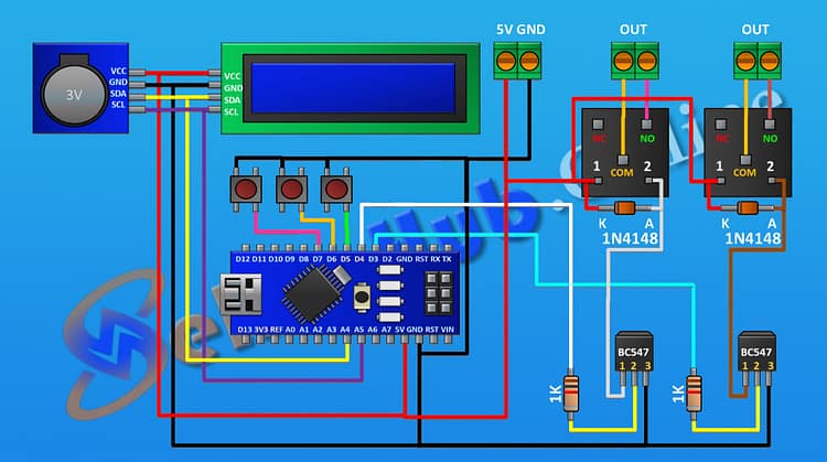
The Two Channel Time Controlled Relay circuit is designed around Arduino, which acts as the central controller. The RTC module keeps track of time, ensuring accuracy. Relays act as the switching devices, controlled by BC547 transistors. Here’s a detailed explanation:
Power Supply: A two-pin terminal block connects the Arduino 5V and GND to power the circuit.
Relay Driver Stage:
Each relay is driven by a BC547 transistor.
A 1kΩ resistor connects the Arduino digital pin (D3 for relay 1, D4 for relay 2) to the transistor base.
The transistor collector connects to one end of the relay coil.
The other coil end connects to Arduino 5V.
A 1N4148 diode is placed across the relay coil to suppress back EMF.
Relay Load Terminal:
A terminal block connects the relay COM and NO pins, where external devices can be wired.
Push Buttons: Three push buttons are added to D5, D6, and D7 with pull-down to GND for manual input (e.g., time set, relay toggle).
Display: The LCD (16×2 with I2C module) connects to Arduino via SDA (A4) and SCL (A5).
RTC Module: Also connected to SDA (A4) and SCL (A5), sharing the I2C bus with the LCD.
This simple configuration allows two devices to be independently controlled based on time.
Download Circuit Diagram
Step-by-Step Hardware Connections
Follow these steps carefully to assemble the Two Channel Time Controlled Relay:
Step 1: Power Supply Setup
Connect a two-pin terminal block.
Connect one pin to Arduino 5V and the other pin to GND.
Step 2: First Relay Driver Circuit
Place BC547 transistor, connect emitter (pin 3) to GND.
Connect a 1kΩ resistor from Arduino pin D3 to base (pin 2).
Connect collector (pin 1) to one relay coil terminal.
Connect the other relay coil terminal to 5V.
Place a 1N4148 diode across the relay coil (cathode to 5V, anode to transistor collector).
Connect relay COM and NO to a terminal block for load connection.
Step 3: Second Relay Driver Circuit
Place another BC547 transistor, connect emitter (pin 3) to GND.
Connect a 1kΩ resistor from Arduino pin D4 to base (pin 2).
Connect collector (pin 1) to one relay coil terminal.
Connect the other relay coil terminal to 5V.
Place a 1N4148 diode across the relay coil (cathode to 5V, anode to collector).
Connect relay COM and NO to a terminal block for load connection.
Step 4: Push Buttons
Button 1: Connect one side to D5, other side to GND.
Button 2: Connect one side to D6, other side to GND.
Button 3: Connect one side to D7, other side to GND.
Step 5: LCD Display (16×2 with I2C)
VCC → 5V
GND → GND
SDA → A4
SCL → A5
Step 6: RTC Module (DS3231/DS1307)
VCC → 5V
GND → GND
SDA → A4
SCL → A5
At this stage, the wiring is complete.
Step 7: Assembly
After making all the connections, I designed a PCB for this project. Then, I placed all the components onto the PCB, soldered them, and completed the circuit.
Gerber Files
Step 8: Final Step
Now, upload the Arduino code to control the relays with real-time scheduling. Once uploaded, the relays will automatically switch ON/OFF based on the set times.
Arduino Code
PCB Assembly
For permanent installation, a PCB can be designed. The PCB layout should have clear tracks for:
Arduino power lines
Relay driver circuits
Diode protection paths
RTC and LCD I2C bus routing
Terminal blocks for external load connections
After soldering all components onto the PCB, double-check connections for shorts or errors.
Working Principle
The RTC continuously keeps track of time. Arduino reads this time and decides when to activate or deactivate the relays.
When the set time matches the internal clock, Arduino outputs a HIGH signal on the corresponding pin (D3 or D4).
The HIGH signal drives the BC547 transistor into saturation, energizing the relay coil.
The relay switches from COM to NO, turning the connected device ON.
When time is over, Arduino turns the pin LOW, de-energizing the relay and switching OFF the load.
The LCD display keeps showing the time and relay status.
Testing the Circuit
Assemble the hardware on a breadboard or PCB.
Power up the Arduino via USB or regulated 5V supply.
The LCD should initialize and display the current time.
Observe the relays clicking ON/OFF as per the pre-set timing.
Use the push buttons to manually test relay toggling or adjust time settings.
Advantages of the Design
Two independent channels for device control
Uses reliable RTC module for accurate timing
Relay isolation for safe switching of higher loads
Easy to expand for more channels
Compact PCB assembly possible
Frequently Asked Questions (FAQs)
1. What is a Two Channel Time Controlled Relay?
It is a circuit that controls two relays (and thus two devices) based on pre-defined time intervals using Arduino and RTC.
2. Why do we use BC547 transistors in this circuit?
Relays require more current than Arduino pins can supply. BC547 transistors act as drivers, amplifying current to energize the relay coils.
3. What is the purpose of the 1N4148 diodes?
They protect the circuit from voltage spikes generated by relay coil switching (flyback effect).
4. Can I increase the number of channels?
Yes, by replicating the transistor–relay driver stage and assigning additional Arduino pins, you can add more channels.
5. Do I need a separate power supply for the relays?
For small relays (5V, low current), Arduino 5V is sufficient. For larger relays, use an external regulated 5V supply with common ground.
6. Why is the RTC necessary?
Arduino alone cannot keep accurate time after power loss. The RTC has a backup battery and ensures reliable timekeeping.
7. Can I build this without PCB?
Yes, it can be built on a breadboard or perfboard for testing, but PCB ensures durability and clean wiring.
Conclusion
The Two Channel Time Controlled Relay project is an excellent way to learn about relay driving, transistor interfacing, and time-based automation. The hardware-only approach makes it easy to assemble without diving into coding details.
By carefully following the step-by-step guide, wiring the circuit, and assembling components on a PCB, you can successfully build your own Two Channel Time Controlled Relay system for reliable timed control.