
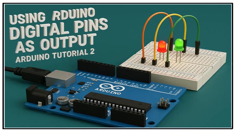
Using Arduino Digital Pins as OUTPUT is a fundamental step in learning microcontroller programming. In this tutorial, we explain how to use Arduino digital pins for controlling LEDs, relays, and external devices. Using Arduino Digital Pins as OUTPUT makes it possible to interface hardware components directly. You will learn step-by-step how to configure pins, write Arduino code, connect circuits, and test results.
Using Arduino Digital Pins as OUTPUT will also help in controlling multiple LEDs, sequential blinking, and connecting relays. This guide ensures you understand digital output basics, transistor interfacing, and relay driving. Using Arduino Digital Pins as OUTPUT is useful in home automation, robotics, and embedded electronics. By practicing different examples, you will gain confidence in programming and circuit building. Using Arduino Digital Pins as OUTPUT is the key to mastering Arduino hardware control.
Introduction
Hi friends, welcome back!
In the previous tutorial of this Arduino series, we learned what Arduino is, how to program it, and made our very first basic project: an LED blinker. If you missed that project, you can check its link in.
In this tutorial, we are going to focus on Using Arduino Digital Pins as OUTPUT. We’ll not only learn the concept but also build example projects — from blinking LEDs on different pins to controlling real-life appliances using a relay.
So without further ado, let’s begin.
What Are Digital Pins in Arduino?

Every Arduino board has digital I/O pins.
These pins can be configured either as INPUT or OUTPUT using the
pinMode()function.When set as OUTPUT, the pins can provide HIGH (5V or 3.3V depending on board) or LOW (0V) signals.
By writing
HIGHorLOWusingdigitalWrite(), you can turn devices ON or OFF.
Revisiting the Blink Code

In the previous tutorial, we uploaded the Blink example code. Let’s break it down again to understand how output pins work.
The first command of this program is in the setup function.
This command is pin mode with M capital and in the parentheses there are two parameters. the first parameter is arduino pin number which we want to set as output or input and the second parameter is the mode in which we want to set our pin. it can be input or output.
So in the first parameter the led built-in is written in capital letters. every arduino board has a built-in led which is mostly connected to pin d13 of arduino.
So led built-in represents pin d13. in the second parameter output is written. so this command is setting pin d13 of arduino as output. at the end of the command a semicolon is written which tells the compiler that the command ends here. in arduino programming we write semicolon at the end of every command. in the loop function the first command is digitalWrite with W capital and in the parentheses the first parameter is led built-in which represents pin d13 and the second parameter is HIGH written in capital letters. so this command will set pin d13 to high.
we have connected led on pin d13 so when this command is executed the led turns on. the next command is delay and in the parentheses 1000 is written. this command will pause the operation for 1000 milliseconds. the number in the parentheses represents milliseconds. the next command is again digitalWrite but the second parameter in this command is LOW written in capital letters. this command will set pin d13 of arduino to low and led will turn off.
The next command is delay for 1000 milliseconds. so this program will blink the led. we can change the speed of led blinking by changing the value of the delay. these are the different blinking speeds with different delay values.
Code Explanation:
pinMode(LED_BUILTIN, OUTPUT);Configures Arduino pin D13 as output.
LED_BUILTINis a constant mapped to pin D13 (built-in LED).
digitalWrite(LED_BUILTIN, HIGH);Turns the pin HIGH (5V), LED turns ON.
delay(1000);Pauses program for 1000 ms = 1 second.
digitalWrite(LED_BUILTIN, LOW);Sets the pin LOW (0V), LED turns OFF.
This cycle repeats in the loop() function, causing the LED to blink.
Changing Pin Number

we can also change the led pin by changing the pin number. let’s connect the led to pin d2 of arduino and change the pin number in the program. so in the pinMode and digitalWrite command the first parameter would be 2.
Instead of using the built-in LED on D13, let’s connect an external LED to D2.
Circuit Connection:
Connect the anode (long leg) of LED → D2 through a 100Ω resistor.
Connect the cathode (short leg) → GND.
Updated Code:
Now your external LED will blink at pin D2.
Example 2: Blinking Two LEDs Alternately

now let’s make another example program.
in this example program we will blink two leds one by one. so let’s connect the leds to pin d2 and d3 of arduino. now let’s have a look at the program. in the setup function we set pin d2 and d3 as output by using pinMode command.
in the loop function first we set pin 2 high and then there is a 1000 millisecond delay which is equal to one second delay.
then we set pin d2 to low then there is another one second delay. then pin 3 goes high and there is a one second delay.
then pin 3 goes low and lastly there is another one second delay.
so in the whole function first one led turns on for one second then it goes off and after one second the second led turns on for one second. then it goes off and after one second the whole sequence repeats again and again.
let’s upload the code and see the result.
Circuit Connection:
LED1 → Pin D2 (via 100Ω resistor) → GND
LED2 → Pin D3 (via 100Ω resistor) → GND
Arduino Code:
Working:
LED1 turns ON for 1 second, then OFF.
After a 1-second delay, LED2 turns ON for 1 second, then OFF.
Sequence repeats endlessly.
Example 3: Controlling High Voltage Devices with a Relay
Arduino pins can supply only 20–40mA at 5V. now as you can see we can control leds with arduino but sometimes we need to control different devices with arduino. those devices can be lights, motors and many other devices.
arduino alone cannot control these devices because these devices consume more power or they run with higher voltage that arduino cannot provide. so to control such devices we can use a relay with arduino.
Circuit Diagram Explanation:
so first we connect a 5 volt relay to breadboard and connect its one coil pin to positive supply. now connect an npn transistor to breadboard which in our case is bc547 transistor and connect its emitter (pin 3) to ground and its collector (pin 1) to second coil pin of the relay.
now connect a diode to coil pins of the relay. the cathode of diode which is its negative pin will be connected to positive supply and its anode will be connected to the collector of transistor. now connect a 10k resistor to breadboard and connect its one pin to pin d2 of arduino and its other pin to base of transistor which is pin 2 of transistor.
Connections:
Arduino D2 → 10k resistor → Base of BC547.
Emitter of BC547 → GND.
Collector of BC547 → One coil pin of relay.
Other coil pin of relay → +5V.
Diode across coil (Cathode to +5V, Anode to collector).
Load (lamp) connected to relay’s NO (Normally Open) contacts with AC supply.
Arduino Code:
Now your Arduino can control AC lamps or other appliances safely using a relay.
Materials for the Project
Applications of Digital Outputs
Blinking LEDs for indication.
Driving relays for home automation.
Controlling motors and pumps via driver circuits.
Activating buzzers and alarms.
Switching DC or AC loads.
Step-by-Step Guide
Connect Arduino to your PC with USB cable.
Build the circuit on a breadboard.
Write or paste the example code.
Select the correct board and COM port.
Upload the code.
Observe LEDs or relay operation.
FAQs
Q1: Can I directly connect a motor to an Arduino pin?
No. Arduino pins provide very little current. Use a relay or motor driver IC.
Q2: Why do we use a resistor with an LED?
To limit current and prevent burning the LED or Arduino pin.
Q3: What is the maximum current an Arduino pin can supply?
Around 20mA recommended, 40mA max.
Q4: Why is a diode used with relay coil?
To protect the transistor and Arduino from back EMF generated when relay coil switches.
Q5: Can I control 220V AC devices with Arduino?
Yes, but only through a relay or optocoupler — never connect directly.
Conclusion
In this tutorial, we explored Using Arduino Digital Pins as OUTPUT with multiple practical examples:
Single LED blink
Two LEDs alternately
Relay control for high-power devices
Now you know how to configure Arduino pins as outputs and use them to control LEDs and external loads. This knowledge forms the foundation for automation, robotics, and IoT projects.
Stay tuned for the next tutorial in this series!