

What is Diode? How Diode Works in Electronics
What is Diode and how diode works are fundamental concepts in electronics. In this detailed guide, we will explain what is diode, its structure, and how diode works in circuits. You will learn about forward bias, reverse bias, threshold voltage, breakdown voltage, and maximum current ratings. We will also explain how to test a diode with a multimeter step by step.
This article on what is diode covers different diode types such as rectifier diodes, zener diodes, light-emitting diodes (LEDs), and Schottky diodes with practical usage. Finally, you will see simple applications of what is diode in AC to DC conversion, device protection, and power regulation. By the end of this guide, you will have complete knowledge of what is diode and how diode works in electronics.
Introduction
Hi friends ,
In this project/article, we are going to learn What is Diode and How Diode Works in electronics.
A diode is one of the most basic and essential semiconductor devices. Despite being small, it plays a very important role in almost every electronic device you use daily. From power supplies to signal processing, diodes are everywhere.
We’ll cover:
- The basic concept of a diode
- Its symbol and pinout
- How a diode works (forward bias, reverse bias)
- Threshold voltage and breakdown voltage
- Testing a diode with a multimeter
- Practical applications of diodes
- Circuit examples
What is Diode?
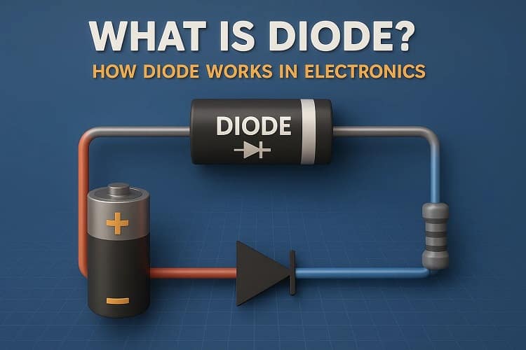
A diode is a semiconductor device with two terminals that only allows current to flow in one direction.
- Anode (+): Positive terminal
- Cathode (−): Negative terminal
Materials known as semiconductors like silicon and germanium are used to make diodes.
Key properties:
- Low resistance in forward direction
- High resistance in reverse direction
Diodes act like electrical check valves, ensuring current flows only where it should.
Symbol of a Diode

The diode symbol consists of:
- Triangle (▶): Represents current flow
- Vertical line (|): Represents the blocking action
Important:
- The arrow indicates the conventional current’s path from the anode to the cathode.
How Diode Works
Let’s break it down step by step:
1. Forward Bias
- When anode (+) is connected to battery positive and cathode (−) to battery negative
- The diode conducts current.
- Current flows after crossing the threshold voltage.
For Silicon diode → Threshold = 0.7V
For Germanium diode → Threshold = 0.3V
2. Reverse Bias
- When cathode (−) is connected to battery positive and anode (+) to battery negative.
- No current flows.
- The diode blocks current like an open switch.
3. Threshold Voltage
- Minimum voltage required for a diode to conduct.
- Below this, no current flows.
- Example: A 7V Zener diode needs 7V before breakdown.
4. Breakdown Voltage
- The reverse voltage at which diode starts conducting heavily in reverse direction.
- Exceeding this value damages a normal diode.
- Zener diodes are specially designed to operate safely at this voltage.
5. Maximum Forward Current
- Every diode has a rated current.
- If exceeded, it heats up and burns out.
Testing a Diode with a Multimeter
Follow these steps:
- Set multimeter to Diode Mode.
- Connect red probe to anode (+), black probe to cathode (−) → A small voltage drop (0.7V for silicon) will be displayed.
- Reverse probes → Display shows OL (open loop) or no conduction.
✔️ If diode shows conduction in both directions → It’s damaged.
BOM (Bill of Materials)
| Component | Quantity | Buy Link |
| 1N4007 Rectifier Diode | 10 pcs | Buy Here |
| 1N4148 Signal Diode | 20 pcs | Buy Here |
| Zener Diode (5.1V, 12V) | 10 pcs | Buy Here |
| LED (Red, Green, Blue) | 50 pcs | Buy Here |
| Schottky Diode 1N5819 | 20 pcs | Buy Here |
Circuit Diagram Explanation
Let’s see a simple diode application:
1. Rectifier Circuit
- Input: AC voltage
- Diode allows current only in one direction → converts AC to DC.
With one diode → Half-wave rectifier
With four diodes in bridge → Full-wave rectifier
2. Protection Circuit
- If a battery is connected in reverse, diode blocks the current.
- Prevents damage to sensitive circuits like microcontrollers.
3. Clipping and Clamping Circuits
- Diodes can shape signals.
- Used in audio processing and waveform modification.
Step-by-Step Guide: Simple Diode Project
We’ll make a reverse polarity protection circuit:
- Take a 9V battery.
- Connect a 1N4007 diode in series with battery output.
- Connect a small LED load.
- If battery is connected correctly → LED glows.
- If battery is reversed → LED remains OFF, circuit protected.
Applications of Diodes
- AC to DC conversion (power supplies)
- Voltage regulation (Zener diode)
- Signal demodulation in radios
- Over-voltage protection
- Logic circuits
- LED lighting
FAQs
1. What is Diode used for?
Diodes are mainly used to control current flow, convert AC to DC, and protect circuits.
2. What is the difference between Zener and normal diode?
A normal diode blocks reverse current, while a Zener diode allows controlled reverse current at breakdown voltage.
3. Can I use any diode in place of another?
No. Each diode has specific voltage and current ratings. Using the wrong one may damage your circuit.
4. How can I test if a diode is damaged?
Use a multimeter in diode mode. If it conducts both ways or not at all, it’s faulty.
5. Why do LEDs glow but other diodes don’t?
LEDs emit light when current passes, while rectifier diodes only conduct electricity.
Conclusion
We learned What is Diode and How Diode Works in electronics.
- A diode conducts in one direction only.
- It has properties like threshold voltage, breakdown voltage, and maximum forward current.
- We can test diodes easily using a multimeter.
- Diodes are widely used in rectifiers, protection circuits, and signal processing.
With this understanding, you can now confidently use diodes in your electronic projects.